Tip and Cantilever
The cantilever is a long beam with a tip located at its apex. In most AFMs the motion of the tip is detected by reflecting a laser off the back surface of the cantilever.
Tip
The tip is generally pyramidal or tetrahedral in shape, and usually made from silicon or silicon nitride. Silicon can be doped and made conductive, allowing a tip-sample bias to be applied for making electrical measurements. Silicon nitride tips are not conducting.
The geometry of the tip greatly affects the lateral resolution of the AFM, since the tip-sample interaction area depends on the tip radius. The radius of the apex of a new tapping mode tip is around 5–15 nm, but this increases quickly with wear. In general the sharper the tip, the higher the resolution of the AFM image.
Cantilever
For contact mode AFM the cantilever needs to deflect easily without damaging the sample surface or tip. Therefore it should have a low spring constant, this is achieved by making it thin (0.3–2 μm). It also needs a high resonant frequency to avoid vibrational instability, so is typically short (100–200 μm). V-shaped cantilevers are often used for contact mode as these can provide low resistance to vertical deflection, whilst resisting lateral torsion.
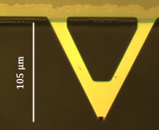
Optical microscopy image of a triangular cantilever
For tapping mode AFM a high spring constant is required to reduce noise and instabilities. Rectangular cantilevers are often used for tapping mode.
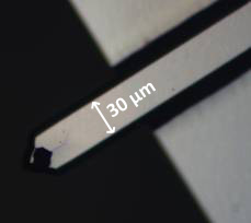
Optical microscopy image of a rectangular cantilever
Detection of cantilever deflection
There are a number of ways to detect the deflection of the cantilever in an AFM. The most common method is using a laser beam. A diode laser is focused onto the back reflective surface of the cantilever, and reflects onto a photodetector. This is position sensitive, and usually has four sectors. The vertical deflection of the cantilever is determined by the difference in light intensity measured by the upper and lower sectors. It is also possible to measure the lateral deflection of the cantilever by the difference between the left and right sectors of the photodetector; this technique is known as lateral force microscopy (LFM).
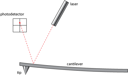
How the deflection of the cantilever is measured