Structure of Bone and Implant Materials (all content)
Note: DoITPoMS Teaching and Learning Packages are intended to be used interactively at a computer! This print-friendly version of the TLP is provided for convenience, but does not display all the content of the TLP. For example, any video clips and answers to questions are missing. The formatting (page breaks, etc) of the printed version is unpredictable and highly dependent on your browser.
Contents
Main pages
Additional pages
Aims
On completion of this TLP you should be able to:
- Understand the biological structure of bone
- Consider bone as an engineering material, its description as a composite and its mechanical properties
- Understand the requirement for hip replacements and the issues involved in selecting implant materials
- Select suitable materials for use in hip replacements
Before you start
Before reading this TLP, you should be familiar with:
- Young’s Modulus (E, Pa), Ultimate Tensile Strength (UTS, Pa), Fracture Energy (Gc, J m-2)
- The concept of composite materials
- Use of Ashby Materials Selection Maps (See the TLP Optimisation of Materials Properties in Living Systems)
Introduction
The properties of biomaterials are very impressive, and in many cases can be compared directly to those of man-made materials, such as in the use of wood for engineering applications, and the use of silk for making light, strong rope. This is all the more remarkable if we consider that biomaterials are entirely self-assembling and form at near ambient temperatures.
Biomaterials are ideally suited to the function that they perform, often aided by a complex hierarchical structure. In many cases this leads to high degrees of anisotropy in the structure and the resultant properties. A good example of this is seen in the structure of bone.
This TLP aims to show you how bone, specifically a human femur, is adapted to the body’s needs and its structural functions. It describes the biology of bone and also considers it as an engineering material.
The second part of the TLP looks at hip implants. Over 50,000 hip replacement operations are performed in the UK each year, and so continues to be a very important area of research and development. This TLP looks at why hip implants are necessary, what the potential problems are with these implants, and considers what properties are necessary for each individual component to arrive at suitable materials for the implant.
Structure and composition of bone
Long bones such as the femur contain two distinct morphological types of bone:
- Cortical (compact) bone
- Cancellous or Trabecular (spongy) bone
These are shown in the figure below.
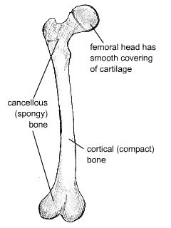
Diagram of distinct morphological types of bone
Cortical bone forms a dense cylinder down the shaft of the bone surrounding the central marrow cavity. While cortical bone accounts for 80% of the mass of bone in the human body, it has a much lower surface area than cancellous bone due to its lower porosity.
Cancellous (or trabecular) bone is located at the ends of long bones, accounts for roughly 20% of the total mass of the skeleton, and has an open, honeycomb structure. It has a much lower Young’s modulus than cortical bone, and this graded modulus gradually matches the properties of the cortical bone to the cartilage that forms the articulating surface on the femoral head.
Composition
Bone itself consists mainly of collagen fibres and an inorganic bone mineral in the form of small crystals. In vivo bone (living bone in the body) contains between 10% and 20% water. Of its dry mass, approximately 60-70% is bone mineral. Most of the rest is collagen, but bone also contains a small amount of other substances such as proteins and inorganic salts.
Collagen is the main fibrous protein in the body. It has a triple helical structure, and specific points along the collagen fibres serve as nucleation sites for the bone mineral crystals. This is shown in the animation below.
The composition of the mineral component can be approximated as hydroxyapatite (HA), with the chemical formula Ca10(PO4)6(OH)2. However, whereas HA as has a Ca:P ratio of 5:3 (1.67), bone mineral itself has Ca:P ratios ranging from 1.37 - 1.87. This is because the composition of bone mineral is much more complex and contains additional ions such as silicon, carbonate and zinc.
Cartilage is a collagen-based tissue containing very large protein-polysaccharide molecules that form a gel in which the collagen fibres are entangled. Articular, or hyaline, cartilage forms the bearing surfaces of the movable joints of the body. Mechanically, articular cartilage behaves as a linear viscoelastic solid. It also has a very low coefficient of friction (< 0.01), largely attributed to the presence of synovial fluid that can be squeezed out upon compressive loading.
The animation below allows you to explore the microstructure of cortical bone.
Stresses
Bones such as the femur are subjected to a bending moment, and the stresses (both tensile and compressive) generated by this bending moment account for the structure and distribution of cancellous and cortical bone.
In the upper section of the femur, the cancellous bone is composed of two distinct systems of trabeculae. One system follows curved paths from the inner side of the shaft and radiates outwards to the opposite side of the bones, following the lines of maximum compressive stress. The second system forms curved paths from the outer side of the shaft and intersects the first system at right angles. These trabeculae follow the lines of maximum tensile stress, and in general are lighter in structure than those of the compressive system.
The thickness of the trabeculae varies with the magnitude of the stresses at any point, and by following the paths of the principal compressive and tensile stresses they carry these stresses economically. The greatest strength is therefore achieved with the minimum of material.
The distribution of the compact bone in the shaft is also due to the requirement to resist the bending moment stresses. To resist these stresses, the material should be as far from the neutral axis as possible. A hollow cylinder is the most efficient structure, again achieving the greatest strength with the minimum of material.
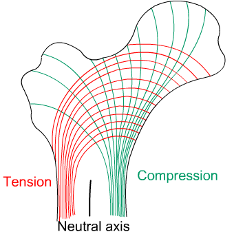
Diagram showing computed lines of constant stress from the analysis of various transverse sections
Formation and remodelling of bone
Bone formation is an essential process in the development of the human body. It starts during the development of the foetus, and continues throughout childhood and adolescence as the skeleton grows. Bone remodelling meanwhile is a life-long process, consisting of resorption (the breaking down of old bone) and ossification (formation of new bone), and is key to shaping the skeleton and to the repair of bone fractures.
There are three types of cell present in bone that are of particular interest – osteoblasts, osteocytes and osteoclasts, which are respectively responsible for the production, maintenance and resorption of bone.
- Osteoblasts
Mononucleated “bone-forming” cells found near the surface of bones. They are responsible for making osteoid, which consists mainly of collagen. The osteoblasts then secrete alkaline phosphatase to create sites for calcium and phosphate deposition, which allows crystals of bone mineral to grow at these sites. The osteoid becomes mineralised, thus forming bone. - Osteocytes
These are osteoblasts that are no longer on the surface of the bone, but are instead found in lacunae between the lamellae in bone. Their main role is homeostasis – maintaining the correct oxygen and mineral levels in the bone. - Osteoclasts
Multinucleated cells responsible for bone resorption. They travel to specific sites on the surface of bone and secrete acid phosphatase, which unfixes the calcium in mineralised bone to break it down.
During foetal development there are two mechanisms for creating bone tissue:
- Endochondral ossification
- Intramembranous ossification
Intramembranous ossification occurs in the formation of flat bones such as those in the skull, and will not be covered further here. More information can be found through the Going Further page.
Endochondral ossification
This involves bone growth from an underlying cartilage model, and is seen in the formation and growth of long bones such as the femur.
The initial step involves the development of a cartilage model, which has the rough shape of the bone being formed. In the middle of the shaft is the primary ossification centre, where osteoblasts lay down osteoid on the shaft to form a bone collar.
The osteoid calcifies, and blood vessels grow into cavities within the matrix. Osteoblasts then use the calcified matrix as a support structure to lay down more osteoid and form trabeculae within the bone. Meanwhile osteoclasts break down spongy bone to create the medullary cavity, which contains bone marrow.
Initially the bone material is deposited with the collagen fibres in random directions, meaning the strength is much lower than at the final stage in which the fibres are aligned. The primary structure is called woven bone because the collagen fibres are woven together randomly. This is then converted into lamellar bone over time, which is much stronger due to the aligned fibres. The osteoid deposited by the osteoblasts calcifies to initially produce primitive cancellous bone. At sites where cortical bone is required, further deposition of osteoid occurs to increase the density of the structure.
At birth secondary ossification centres appear at either end of long bones. Between the primary and secondary centres is the epiphyseal plate, made of cartilage, which continues to form new cartilage and be replaced by bone such that the bone increases in length. This continues until a person is in their mid-twenties, when the plate is finally replaced by bone and no further growth occurs.
Remodelling of bone
Ossification is also essential in the remodelling of bone. This occurs throughout a person’s lifetime, with ossification and resorption (removal of bone tissue) working together to reshape the skeleton during growth, maintain calcium levels in the body, and repair micro-fractures caused by everyday stress.
The remodelling of cortical bone follows the same process as shown above, but with a different geometry in order to form the concentric lamellae seen in osteons.
Responsive material
Bone is considered to be a responsive material. The formation and resorption of bone occur continuously: the body responds to stress levels in different areas of bone to ensure the right amount of healthy bone tissue is maintained and the bone can be continually reshaped.
A stress of 25–40 MPa is sufficient to maintain the correct levels of bone. If the bone is under-stressed for prolonged periods of time, bone wastage will set in, and the bones will become thinner. This can be an issue if a patient is bed-ridden for a long time, and is also observed in astronauts after long periods in space. A similar effect occurs during osteoporosis, in which the activity of osteoblasts decreases with age. This results in an imbalance of resorption and formation, causing bones to become thinner and weaker.
The opposite effect can be seen when bones are suddenly subjected to higher levels of stress than normal. Studies have been conducted that show an increase in bone mass in new recruits to the army as they begin intensive training.
Mechanical properties of bone
Introduction
Although an organic material, bone can often be considered in the same way as man-made engineering materials. However, due to the nature of its synthesis it is likely to show more variation in measured properties than typical engineering materials. Factors include:
- Age
- Gender
- Location in the body
- Temperature
- Mineral content
- Amount of water present
- Disease, e.g. osteoporosis
These variables can to an extent be dependent on each other. For example, the mineral content will vary according to the bone’s location in the body, and with the age of the patient.
As humans age, their bones typically become less dense and the strength of these bones decreases, meaning they are more susceptible to fracture. Osteoporosis is a disease involving a marked decrease in bone mass, and it is most often found in post-menopausal women.
These variables mean that there is a range of measured properties for bone, and so values given in tables will always be an average, with quite a considerable spread possible in the data.
In addition, the anisotropic structure of bone means that its mechanical properties must be considered in two orthogonal directions:
- Longitudinal, i.e. parallel to osteon alignment. This is the usual direction of loading
- Transverse, i.e. at right-angles to the long axis of the bone
Modulus
Bone can be considered to consist primarily of collagen fibres and an inorganic matrix, and so on a simple level it can be analysed as a fibre composite.
Composites are materials that are composed of two or more different components. They are commonly used in engineering and industry where the combination of the two materials creates a composite with properties that are superior to those of the individual components.
The Young’s Modulus of aligned fibre composites can be calculated using the Rule of Mixtures and the Inverse Rule of Mixtures for loading parallel and perpendicular to the fibres respectively.
RULE OF MIXTURES
Eax = f Ef + (1 - f) Em
INVERSE RULE OF MIXTURES
\( E_{ax} = \left[ {\frac{f}{{E_f }} + \frac{{\left( {1 - f} \right)}}{{E_m }}} \right]^{ - 1} \)
Where
Ef = Young’s Modulus of fibres
Em = Young’s modulus of matrix
Eax, Etrans = Young’s Modulus of composite in axial and transverse directions
f= volume fraction of fibres
For the full derivation of these rules, click here.
These formulae predict that the composite will be stiffer in the axial direction than the transverse, so cortical bone will be stiffer in the direction parallel to the osteons (i.e. parallel to the long axis of the bone).
The chart below shows calculated values for the Young's Modulus of bone in both the longitudinal and transverse directions, for a range of fibre volume fractions, as well as the actual values.
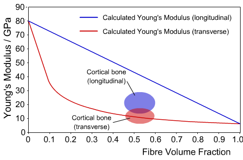
Calculated and experimental values of Young’s Modulus for cortical bone
We can see that for the transverse direction, the composite model closely agrees with experimental values. However, in the longitudinal direction the difference is large, indicating the model does not give an accurate picture of the behaviour of bone.
This difference occurs because the composite model of the microstructure of bone is highly simplified, since the collagen fibres are not aligned parallel to the axis of the osteons, and the bone mineral exists as discrete crystals, rather than forming a continuous matrix.
A better approximation would be to model bone as a two level composite. One level is provided by hydroxyapatite-reinforced collagen in a single osteon, and the second level is obtained by the approximately hexagonal packing of osteons in a matrix of interstitial bone.
The actual values for the Young’s modulus of bone, compared to collagen and hydroxyapatite, are shown in the table below. The measured value of Young’s Modulus also depends on temperature, decreasing with an increase in temperature, and the strain rate, increasing in value with an increase in strain rate.
Material |
Young’s Modulus, E (GPa) |
Collagen (dry) |
6 |
Bone mineral (Hydroxyapatite) |
80 |
Cortical bone, longitudinal |
11-21 |
Cortical bone, transverse |
5-13 |
Tensile and Compressive Strength
As mentioned previously, bones such as the femur are subjected to bending moments during normal loading. These create both tensile and compressive stresses in different regions of the bone.
There is a large variation in measured values of both the tensile and compressive strength of bone. Different bones in the body need to support different forces, so there is a large variation in strength between them. Additionally, age is an important factor, with strength often decreasing as a person gets older.
|
Longitudinal direction |
Transverse direction |
Tensile strength (MPa) |
60-70 |
~50 |
Compressive strength (MPa) |
70-280 |
~50 |
Elasticity
Bone mineral is a ceramic material and exhibits normal Hookean elastic behaviour, i.e. a linear stress-strain relationship. In contrast, collagen is a polymer that exhibits a J-shaped stress-strain curve. (See the TLP Elasticity in Biological Materials.
Typical stress-strain curves for compact bone, tested in tension or compression in the wet condition, are approximately a straight line. Bone generally has a maximum total elongation of only 0.5 - 3%, and therefore is classified as a brittle rather than a ductile solid.
Fracture Toughness
In contrast to the findings for tensile and compressive strength and modulus, the values of toughness in the transverse direction are generally higher than those in the longitudinal direction. This is due to the presence of the cement lines in the microstructure. These are narrow regions around the outermost lamellae in the osteons, and they form the weakest constituent of bone. Crack propagation parallel to the osteons can occur much more easily through these regions and this significantly decreases the fracture toughness of cortical bone in the longitudinal direction. If a crack is propagating perpendicular to an osteon it will change direction when it reaches a cement line, thus blunting the crack. This is illustrated in the animation below.
As a result, although bone is classified as a brittle material (with the major component being mineral), its toughness is excellent. Bone’s fracture energy, Gc, is approximately 1.5 kJ m-2, which is comparable to steel at low temperatures and wood when measured parallel to the grain. This is much tougher than man-made ceramics due to the presence of the collagen fibres in bone. Since the stress-strain curves for loading and unloading are different the elasticity is therefore time-dependent, a common feature of fibrous proteins. For a full discussion of this see the TLP Elasticity in Biological Materials.
Bone replacement
Bone replacement materials can be needed for a variety of reasons. They are sometimes required when a section of bone is missing and the gap needs to be filled in, for example following an accident or after the removal of a tumour.
There are several options for this type of bone replacement:
- Allografts involve using material from another patient. However, there are risks of infection and the implant being rejected, and the strength of the replacement bone may be reduced due to sterilisation.
- Autografts involve using material from the same patient, but from a different site (such as the pelvis). Although this reduces the chances of rejection, there is a limited amount of material available, and two surgical procedures are needed, leading to more pain and a higher risk of infection.
- Synthetic materials are gradually becoming more popular. Hydroxyapatite can be prepared easily in a laboratory, but since it is a ceramic, it is too brittle to be used on its own for large-scale applications. Composites of hydroxyapatite with degradable polymers can also be used, which resorb over time and allow bone to regrow and fill the space.
However, it is often not as simple a situation as needing to fill in a gap in an otherwise healthy bone, and other reasons for bone replacement materials being required are often age-related. Arthritis is a condition usually associated with old age in which the cartilage at joints wears away, meaning the bones at joints can rub against each other, causing pain and decreased mobility. Additionally, as people get older, their bones become more brittle, and they can experience extensive loss of bone mass (osteoporosis) that leaves them with an increased risk of a hip fracture. This is particularly true for female patients.
In these situations, it is impossible to repair the existing bone and joint replacements are often required. Hip replacement is one of the most common implant surgeries, and this example will be discussed throughout the remainder of this TLP.
An introduction to hip replacements
There are two main parts to a total hip replacement implant. The femoral component fits into the top of the femur and replaces the ball of the ball-and-socket joint. The acetabular cup sits in the pelvis and replaces the socket. This is shown in the diagram and micrographs below.
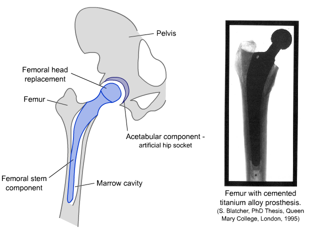
Diagram and radiograph of a hip replacement
The femoral component is fitted by inserting it into the shaft of the femur, which is prepared by hollowing out a section to fit the stem of the implant. The femoral stem essentially replaces bone in the femur and has a structural role that requires it to match, as closely as possible, the strength and toughness of the natural bone.
The requirements for the femoral head component are that it must have a very particular shape, which fits exactly within the replacement socket, and the surface should have a low coefficient of friction.
The acetabular cup component sits in the hip socket and replaces the worn cartilage. Therefore, this part must itself have a low wear rate and must also minimise wear of the femoral head component.
It is therefore likely that these three components will be made from different materials and choosing materials with the correct properties is very important.
Selecting implant materials
There are four main criteria to consider when selecting suitable implant materials.
- Biological Conditions
The human body is not an easy environment for a material to function in for prolonged periods. It must be able to operate for many years at a temperature of 37°C in a very moist environment.
- Response
Implant materials must be designed to minimise the adverse reactions associated with introducing a foreign material to the body. The immune system will typically attack anything that has originated outside the body, leading to inflammation. Elevated levels of particular metals in the bloodstream can lead to various problems including cytotoxicity and carcinogenesis. It is therefore crucial to choose materials that will have a minimal negative impact on the body.- Cytotoxicity - Having a toxic effect on cells, caused by increased levels of metal ions in the bloodstream.
- Carcinogenesis - The formation of cancerous cells, which can be caused by elevated levels of certain metal ions in the body.
- Materials Properties
The materials used in each component of the hip implant must have suitable properties to allow them to replace the natural tissue and continue to perform the same functions.
The mechanical property requirement for the femoral stem is primarily to support the loads that are applied, and therefore the modulus of the implant material is one of the main criteria. The femoral head and acetabular cup components are required to act as bearing surfaces, and therefore, the coefficient of friction and wear rates of these materials will be important.
- Cost
As with most areas of materials science, cost is an important contributing factor to the selection of materials. Often, manufacturers must strike a suitable balance between a material’s performance and cost.
These issues are discussed in the following two sections, along with information about the materials that are generally chosen for these components.
Materials selection of femoral stem component
The femoral stem component replaces a large portion of bone in the femur, and this is therefore the load-bearing part of the implant. To bear this load, it must have a Young’s Modulus comparable to that of cortical bone. If the implant is not as stiff as bone, then the remaining bone surrounding the implant will be put under increased stress. If it is stiffer than bone, then a phenomenon known as stress shielding will occur.
Stress Shielding
As discussed earlier, bones are constantly being reshaped by osteoblasts and osteoclasts, through the continual formation and resorption of bone material.
If the implant is much stiffer than the bone, then the implant will bear more of the load. Because the bone is shielded from much of the stress being applied to the femur, the body will respond to this by increasing osteoclast activity, causing bone resorption.
Due to its higher surface area, cancellous bone is more biologically active because the cells involved in the formation and destruction of bone are found on the surface only. It is therefore more quickly and more drastically affected by stress shielding, wasting away up to four times as quickly as cortical bone.
Suitable Materials
Although 70 wt% of bone material is a ceramic, hydroxyapatite ceramics are not suitable materials for femoral stem replacements, as they are much too brittle. Polymers are also unsuitable as they are prone to suffer from creep and fatigue.
Metals are generally used because they typically have a high Young’s Modulus, are tough and ductile meaning they yield before breaking, and have good fatigue resistance. They do, however, tend to be much stiffer than bone, which can lead to stress shielding.
A useful tool for comparing the mechanical properties of different materials is the materials selection map. Full instructions on how to use these are given in the TLP Optimisation of Materials Properties in Living Systems.
Below are two Materials Selection Maps showing some of the most commonly considered metals for femoral stem replacements.
As can be seen from the selection map, steel has a Young’s modulus much higher than that of bone, meaning that stress shielding is a serious issue. Stainless steel was used for the femoral component in the earliest hip replacements, and is still used in some implants today. It is an alloy of iron, chromium and usually nickel and cobalt. It is resistant to corrosion, abundant and relatively cheap and easy to produce. However, some people have allergies to nickel, which would cause extreme adverse reactions after the implant operation.
A cobalt-chromium-molybdenum alloy was later introduced as an alternative, since it had better wear properties than stainless steel. However, it is a harder metal, meaning it is more difficult to machine, and it is much more expensive.
Titanium’s modulus is only half that of stainless steel, so the remaining bone will suffer less from stress shielding. It has an excellent strength to weight ratio and an impressive resistance to corrosion. Titanium is also biologically inactive and resistant to creep deformation, and these advantages over stainless steel make it a very good choice of material for the femoral stem component. It is, however, significantly more expensive than stainless steel, costing up to five times as much per kilogram (although in making a hip implant a smaller mass of titanium would be used than steel).
Rather than using commercial purity (cp) titanium, the alloy Ti-6Al-4V (titanium alloy with 6% aluminium and 4% vanadium by weight) is often used as it gives increased toughness, as shown, and improved fatigue resistance.
This alloy can also be treated during the sintering process in a way that controls its porosity. Porosity is the ratio of the volume of pores in a material to the volume of the whole material, and the value of the Young’s Modulus decreases with increasing porosity. As can be seen from the first Materials Selection map, a porosity of 40% gives properties which match those of cortical bone extremely well.
Fixation
The femoral stem component is inserted into the femur, which has been prepared to fit the component. This is traditionally bound to the bone with a polymer bone cement, polymethylmethacylate (PMMA). As well as fixing the implant in place, the cement helps distribute load more evenly between the implant and bone. The drawback with this method is that during the curing process (hardening through the cross-linking of polymer chains) a large amount of heat is released that can cause necrosis (cell death) in the bone around the implant and lengthen recovery time.
Rather than using bone cement, an alternative fixation method is to introduce a porous surface layer to the implant, which encourages bonding by allowing bone to grow into the pores. The bone and implant therefore become integrated, meaning that the implant is less prone to loosening.
A further modification is to coat the implant with a layer of hydroxyapatite. Since its chemical composition is similar to that of bone mineral, the coating enhances bone growth. Many surgeons now favour these uncemented implants as they give a quicker recovery time, with many patients able to put weight on their hip the day after surgery.
Coating with hydroxyapatite does raise some problems of its own, however. The coating is done at an elevated temperature, and as the implant cools, the alloy and the HA contract at different rates, because hydroxyapatite’s thermal expansion coefficient is higher than that of the titanium alloy. This can generate thermal stresses and cause cracking of the surface of the implant. In an attempt to match the thermal expansion coefficients (and so avoid cracking), manganese can be added to the alloy to raise its expansion coefficient.
Materials selection of femoral head and acetabular cup components
The choice of design for the femoral head and acetabular cup components can be broken down into two main categories: hard-on-hard and hard-on-soft. Hard-on-hard describes implants in which both components are made from either metal or ceramic, and hard-on-soft describes those in which the femoral head is made of a metal or ceramic and the acetabular cup is a polymer.
Hard-on-Hard Implants
Metal-on-metal implants were first developed in the 1960s but have since been greatly improved. Cobalt chrome is a popular choice, although some studies have found that metal-on-metal implants can cause elevated levels of the metal ions in urine and the bloodstream. This indicates that wear produces particles that enter the body, and which may have an adverse effect. This is particularly a problem for people with poor kidney function.
Another possibility is implants in which both the femoral head and the acetabular components are made from a ceramic, such as alumina or zirconia. The main issue to note with these is that the ball and the cup must be manufactured as a pair. They must exactly fit one another, otherwise chipping will occur, and ceramic particles will be present in the joint.
Hard-on-Soft Implants
Early implants had a metal femoral head and an acetabular component made from ultra high molecular weight polyethylene (UHMWPE), and this is still one of the most popular styles of implant. UHMWPE has densely packed linear polyethylene chains, which gives increased crystallinity and improved mechanical properties, although it leads to a decrease in ductility and fracture toughness. The main problem with this combination of materials is wear of the acetabular cup, which can lead to the formation of small particles of the polymer and inflammation. A further operation may be also be required at a later date to replace the worn component. Studies have shown that increasing the cross-linking in the polyethylene significantly reduces wear, leading to more durable acetabular components, thus increasing the lifetime of an implant
Alternatively, ceramics such as alumina or zirconia can be used to manufacture the femoral head. These can be polished to give a very smooth surface and have a much lower wear rate than metal on polyethylene. These improved wear properties are dependent on a small, uniform grain size in the ceramic, so its microstructure must be carefully controlled during the manufacturing process.
Summary
- Bone is a biomaterial with a complex hierarchical structure, which gives it some impressive material properties.
- It is primarily composed of a bioceramic (similar to hydroxyapatite) and collagen, a fibrous protein.
- At a microscopic level, it can be seen that the collagen-bone mineral composite forms concentric lamellar structures known as osteons, which are the main structural element of bone. The osteons are densely packed together in cortical bone and their long axes tend to run parallel to the long axis of the bone.
- In common with many biomaterials, bone is anisotropic: its mechanical properties differ depending on the orientation of the sample being tested.
- Hip replacements are a very common surgical procedure, particularly among older people, as bones can become more brittle with age.
- There are three main parts to a total hip replacement: the femoral stem, femoral head, and acetabular components.
- The main challenge with hip replacements is to find a material that has mechanical properties similar to that of bone, is capable of operating for many years in the biological conditions in the human body, and causes minimal adverse host response from the body.
- The femoral stem is the main load-bearing component. Increasingly the titanium alloy Ti-6Al-4V with 40% porosity is used, as it combines excellent material properties with the advantage of being, to a large extent, biologically inert.
- The main mechanical requirement of the femoral head and acetabular cup is to minimise wear. The femoral head is generally a highly polished metal or ceramic, and the acetabular cup is usually made of UHMWPE - a dense, crystalline polyethylene.
You should note that no one material or design has emerged as the definitive hip replacement; each has its own advantages and disadvantages, which must be considered for each individual patient taking into account their age, general health and lifestyle. Also, as is often the case, cost is a very important factor for biomaterials companies, with superior mechanical properties sometimes being sacrificed for ease of production.
Questions
Quick questions
You should be able to answer these questions without too much difficulty after studying this TLP. If not, then you should go through it again!
-
Bone is a composite of a mineral which can be approximated to hydroxyapatite, and which protein?
-
Which component of the hip implant is often made from ultra high molecular weight polyethylene?
-
A titanium alloy is often used for the femoral stem component of the hip implant. Which other metals are present in this alloy?
-
Fracture of bone occurs most easily:
Deeper questions
The following questions require some thought and reaching the answer may require you to think beyond the contents of this TLP.
-
Which of these statement(s) is/are true?
-
Which of these statement(s) is/are true?
-
Hydroxyapatite has a density of 3.16 Mg m-3 and collagen's density is 1.33 Mg m-3. Using the weight percentages for dry bone given, calculate the volume fractions of bone mineral and collagen in cortical bone.
Use these volume fractions and the Young's Moduli of these components to calculate a value for the Young's modulus of dry cortical bone.
Explain any difference between this and the value quoted in the TLP. -
In this diagram of the top of a femur, the thickness of the cortical bone in the main shaft of the femur is marked.
This thickness is roughly 1 cm, with the marrow space located in the centre.
Using this diagram, make estimates of the maximum stress generated in the femur when
(A) standing still
(B) walking down stairs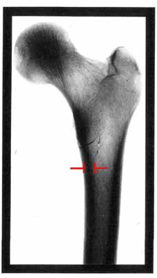
(S. Blatcher, PhD Thesis, Queen Mary College, London, 1995)
Going further
Books
| Title | Author | Publisher |
| Biomaterials Science | Ratner et al | Academic Press (1996) |
| Introduction to Bioceramics | Hench, Wilson | World Scientific (1993) |
| Bone Engineering | Davies | em squared Inc. (2000) |
Websites
- NASA
page on Bones in Space
- NASA on Space Research Builds Stronger Bones
- If you are interested in knowing more about the formation of bone
- Website which includes a 3D animation of the hip replacement process
Derivation of the rule of mixtures and inverse rule of mixtures
Consider a simple model of a continuous fibre composite in which the fibres and matrix are each represented as solid blocks with volumes proportional to their relative abundance in the composite.
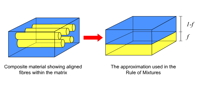
Axial loading
Now, if we consider a force applied in a direction parallel to the long axes of the fibres, the strain on the fibres must equal the strain on the matrix. These strains are in turn equal to the total strain on the composite,
εax = εf = εm (i)
As \(\varepsilon = \)\(\frac{\sigma }{E} \) (ii)
\[ \varepsilon _{ax} = \varepsilon _f = \frac{{\sigma _f }}{{E_f }} = \varepsilon _m = \frac{{\sigma _m }}{{E_m }} \tag{iii} \]As stress is force per unit area, it can also be seen that the overall stress,
σax = f σf + (1 - f) σm (iv)
Combining equations (iii) and (iv) gives an expression for the axial Young’s Modulus
Eax εax = f Ef εf + (1 - f) Em εm (v)
and since εax = εf = εm
Eax = f Ef + (1 - f) Em (vi)
This is known as the Rule of Mixtures.
Transverse loading
A similar approach can also be used to find an expression for transverse stiffness if the load is applied perpendicular to the fibres.
In this case an equal stress assumption is made,
σtrans = σf = Ef εf = σf = Em εm (vi)
The overall strain in the composite is:
εtrans = f εf + (1 - f) εm (viii)
The transverse modulus of the composite is then given by:
\[ E_{trans.} = \frac{{\sigma _{trans} }}{{\varepsilon _{trans} }} = \frac{{\sigma _f }}{{f\varepsilon _f + (1 - f)\varepsilon _m }} = \left[ {\frac{f}{{E_f }} + \frac{{(1 - f)}}{{E_m }}} \right]^{ - 1} \]
This is known as the Inverse Rule of Mixtures. It is not as accurate as the Rule of Mixtures because the equal stress assumption is not entirely valid – parts of the matrix will be shielded from stress by the fibres.
Academic consultant: Jacqui Capes (ex-University of Cambridge), Jessica Gwynne (University of Cambridge)
Content development: Catherine McCloskey and Tom Furnival
Web development: David Brook and Lianne Sallows
This DoITPoMS TLP was funded by the UK Centre for Materials Education and the Department of Materials Science and Metallurgy, University of Cambridge.