Liquid Crystals (all content)
Note: DoITPoMS Teaching and Learning Packages are intended to be used interactively at a computer! This print-friendly version of the TLP is provided for convenience, but does not display all the content of the TLP. For example, any video clips and answers to questions are missing. The formatting (page breaks, etc) of the printed version is unpredictable and highly dependent on your browser.
Contents
Main pages
Additional pages
Aims
On completion of this TLP you should:
- Know the basic characteristics of liquid crystals, as well as the types of molecules capable of forming them.
- Be aware of the different degrees of order that can be present in a liquid crystal.
- Understand the various optical properties of liquid crystals, and how they are affected by factors such as molecular shape and defects within a sample.
- Be aware of some of the technological applications of these materials.
Before you start
This TLP is mostly self-explanatory, however familiarity with the Optical Microscopy TLP as well as the concept of refractive indices is recommended.
Introduction
Liquid crystals, as their name implies, are substances that exhibit properties of both liquids and crystals. Specifically, their molecules have the high orientational order found in crystalline solids as well as the low positional order found in liquids or amorphous glasses.
Most liquid crystals are thermotropic; their degree of orientational and positional order depends on temperature and so their liquid crystalline phase occurs within a limited temperature range between the solid and liquid phase.
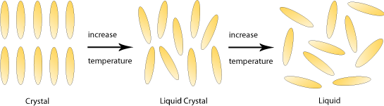
Liquid crystal molecules are typically ‘rod shaped’ – long and thin with a rigid centre that allows them to maintain their shape. They also have flexible ends, which means that they can still flow past each other with ease. Molecules with this shape are known as calamitic liquid crystals.
It is also possible to find liquid crystals made up of disc-shaped molecules; these are given the name discotic liquid crystals. The same rules apply here – a rigid centre is essential in order for the molecule to keep its shape and flexible edges allow ease of movement. Furthermore, polymeric liquid crystals as well as those whose behaviour depend on their concentration in solution (lyotropic liquid crystals) have also been discovered.
For the purposes of this TLP we will be concentrating on calamitic (rod-shaped) liquid crystals only, however similar principles can be applied to all types of liquid crystal mentioned above.
Order and disorder – molecular orientation
Due to their distinctive shape calamitic liquid crystal molecules undergo stronger attractive forces when arranged parallel to one another. They therefore tend to align themselves pointing along one particular direction; this is a known as the director vector and is given the notation n. The angle between individual liquid crystal molecules and the director gives an indication of the orientational order of the system, which can be calculated using the following formula:
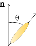 \({\rm{order}}\;{\rm{parameter}}\;Q = {{(3\left\langle{{\cos }^2}\theta \right\rangle - 1)}} \;/\;{2}\)
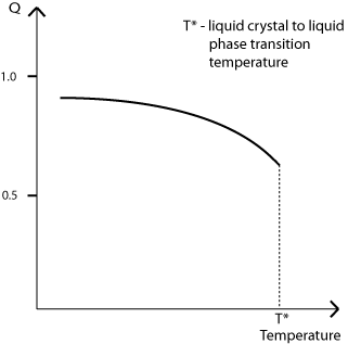
When Q = 1 the liquid crystal has complete orientational order; when Q = 0 it has no orientational order and has therefore become an isotropic liquid.
For a thermotropic liquid crystal the variation of Q with temperature follows a trend similar to the one shown in the diagram below (exact values will vary):
Order and disorder – molecular position
In the introduction we stated that whilst liquid crystals have high orientational order, their positional order is very low. However certain positional arrangements are possible. In general, calamitic liquid crystals can be divided into three different mesophases:
Nematic: |
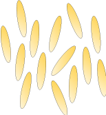 |
Smectic: Smectic liquid crystals consist of molecules arranged into separate layers. However, there is no further positional order within the layers themselves. |
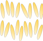 |
Chiral Nematic: |
 |
As we will later see, the different degrees of positional ordering lead to very different optical properties.
Defects
Just like regular crystal lattices, liquid crystals can contain defects these are given the name disclinations.
Normally liquid crystals are most stable when all of the molecules are aligned to point along a single director. However, external factors can force the direction of the director vector to change abruptly somewhere within the sample (such factors include external electric/magnetic fields or even the rigid sides of the container itself). Where this occurs the local director is said to be undefined, and the region in question is the disclination. The stability of a disclination is dependent on the Frank Free Energy of the liquid crystal – however discussion of this particular topic is beyond the scope of this TLP.
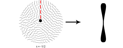
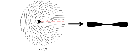
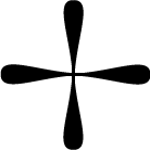
Some of the possible disclinations in a nematic liquid crystal are shown in the diagrams below (the dot indicates the location of the disclination itself whilst the lines represent the surrounding liquid crystal molecules and their orientations). Each type is assigned a number and a sign; the number indicates the strength of that particular disclination whilst the sign tells us which disclinations are capable of cancelling each other out should they come into contact (for example, the s = ½ and s = -½ disclinations could annihilate to produce a region with no defects).
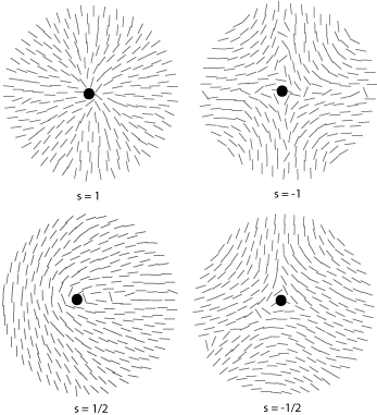
From the above diagrams we can therefore identify the disclination in the cover picture of this TLP as s = -1/2.
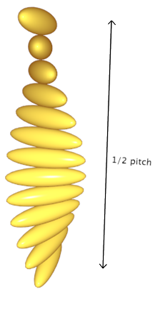
In actuality disclinations are 3-dimensional phenomena; the following 3D models are of s = 1 and s = -1 disclinations where the liquid crystal is constrained within a particular environment:
|
View an s = 1 point disclination (such as in a small spherical droplet) |
View an s = -1 point disclination (such as in a small spherical droplet) |
|
View an s = 1 line disclination (such as in a capillary tube) |
View an s = -1 line disclination (such as in a capillary tube) |
The concept of disclinations in liquid crystals is analogous to that of a dislocation in solid materials. The TLP Introduction to Dislocations covers this particular topic in more detail.
Optical properties – birefringence in nematics
One factor common to all liquid crystals is anisotropy; this in turn means that all liquid crystals will have a property known as birefringence.
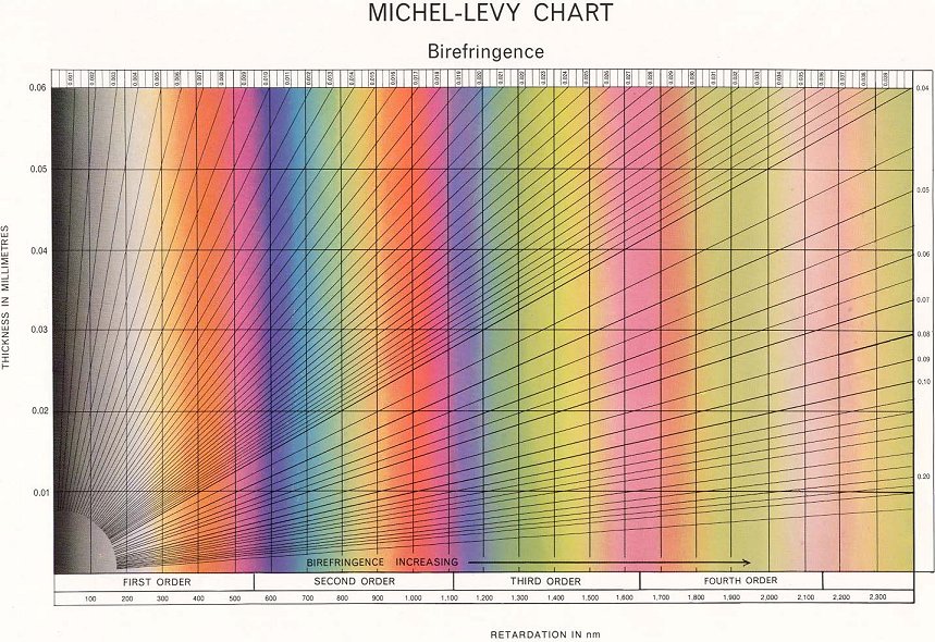
The result is that, for a given sample with a certain thickness and birefringence, when observing it through crossed polars we will see a colour made up of all the wavelengths of light that aren’t blocked by the analyser. Using tools such as the Michel-Levy Chart we can see which colours apply to which blocked wavelengths and thicknesses – this in turn tells us the birefringence of the particular liquid crystal.
Looking at an image of a nematic liquid crystal we do not actually see colours – rather a bright white with several dark patches.
This is because the birefringence if a typical nematic at most temperatures is so great that we do not see much colour, but rather ‘high order white’ (seen to the right of the Michel-Levy Chart). The dark regions occur when the orientation of the director is completely parallel or perpendicular to one of the polarisers – in these regions the light passing through the sample only experiences one refractive index and so behaves as if it were passing through an isotropic liquid.
This effect can be seen in the demonstration below. It is a ‘virtual optical microscope’ – by rotating the sample we can observe the regional variations in brightness as the different local director vectors move in and out of being in parallel with one of the polarisers (i.e. every 90° areas that were the lightest become the darkest and vice versa).
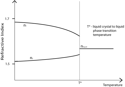
Note that the birefringence (n1 – n2) of a nematic liquid crystal is dependent on its temperature. As shown on the diagram below, it decreases with increasing temperature, meaning that the most colours will be seen when the sample is held close to T*.
Optical properties – birefringence in chiral nematics
Chiral nematic liquid crystals also exhibit birefringence – however due to their chirality the manner in which they split light into components is slightly different.
When light is travelling along the helical axis of a chiral nematic it does not undergo regular (‘linear’) birefringence. This is because as the director vector rotates the two components rotate along with it, and having travelled through one 360° pitch the components experience exactly the same overall refractive index. The result is that one component does not end up travelling faster than the other and so we see no optical path difference.
However, in a chiral material light can become circularly polarised. In this case the light is split not into two perpendicular components, but instead into two components that are constantly rotating in opposite directions. The difference between linear polarisation (as in a nematic) and circular polarisation (as in a chiral nematic) is illustrated in the demonstration below. (The overall polarisation is indicated by the blue vector labelled S, whereas the red vectors indicate the components along the permitted vibration directions PVD1 and PVD2. The black colouring indicates when the vectors are moving in the opposite direction.)
Optical properties – observing defects
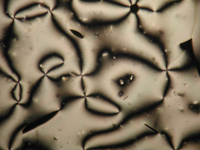
A further property of nematic liquid crystals when viewed using polarised light microscopy is the appearance of schlieren brushes; these are the distinctive dark cross shapes that appear throughout the image below.
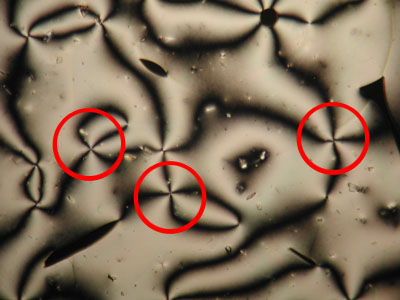
The centre of a cross is in fact a disclination in the liquid crystal, the surrounding dark regions occurring where the orientation of the crystals is parallel to either the polariser or analyser.
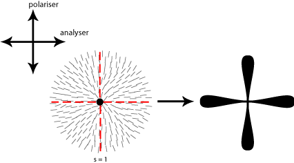
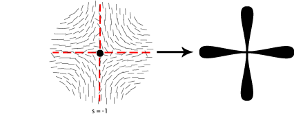
In order to work out which type of cross corresponds to which type of disclination we therefore need to think about the orientation of the local directors relative to a given set of crossed polars. This is shown for four different disclinations below:
A further property of disclinations in nematic liquid crystals is that when one of the polarisers is rotated the schlieren brushes appear to rotate themselves; furthermore disclinations with opposite signs can be differentiated by the fact that their brushes appear to rotate in opposite directions. This is demonstrated in the video below:
Video of the movement of schlieren brushes in a nematic liquid crystal
Observing phase transitions
As mentioned in the introduction, the liquid crystalline phase usually occurs in a small temperature range between the solid and liquid phases. In the following section we are going to observe this phase transition using MBBA,  which is a nematic liquid crystal between 21°C and 48°C.
In each of the following experiments a microscope slide containing MBBA is heated until it becomes an isotropic liquid. It is then observed between crossed polarisers as it is allowed to cool down to room temperature.
Experiment 1 uses regular MBBA on a regular glass slide;
Experiment 2 uses regular MBBA on a slide with parallel scratches on its surface;
Experiment 3 uses MBBA mixed with Canada balsam (a chiral glue) on a regular glass slide.
Experiment 1: Isotropic Liquid to Nematic Liquid Crystal
Video of the phase transformation (20x magnification, 3x speed)
- Note that as the temperature decreases the coloured liquid crystalline phase begins to nucleate at various random points across the slide (remember that the colours seen during the transition occur due to birefringence).
- As described in previous section, darker regions are visible where the director is aligned with either the polariser or the analyser.
- The video above is at too low a magnification to confidently identify any schlieren brushes. In the video sequence below, another sample is recorded forming at a higher magnification:
View Part 1 of the phase transformation in another sample
|
Video of part 1 of the phase transformation in another sample |
Video of part 2 of the phase transformation in another sample |
- Finally, towards the end of the video we can see that the different regions of the liquid crystal are still drifting around, albeit slowly. This shows how fluid the MBBA is, despite having entered the liquid crystalline phase (high fluidity is another characteristic of nematics).
Experiment 2: Isotropic Liquid to Nematic Liquid Crystal (On Grooved Surface)
Video of the phase transformation (20x magnification, 4x speed)
- The elongated liquid crystal molecules tend to orientate along the scratches – this is why we now see uniform extinctions rather than various ‘blotches’ of darkness.
- Nucleation of the liquid crystalline phase is also guided by the scratches, with the liquid crystal sweeping in from the side rather than appearing at random points.
Experiment 3: Isotropic Liquid to Chiral Nematic Liquid Crystal
Video of the phase transformation (20x magnification, 3x speed)
- Note how different the growth and final appearance of the liquid crystalline phase is, even when the only change to the sample is the addition of a chiral liquid.
- Although nucleation begins in a similar fashion to the regular nematic, we can see the different regions merge with one another to form the final ‘fingerprint structure’ that is characteristic of chiral nematics with their helical axis parallel to the surface of the slide.
- Circular birefringence only occurs when the light is travelling up the helical axis; therefore in this case the lines we are seeing are actually turns of the helix.
Note that there also exist phase transitions between different degrees of ordering (e.g. a smectic à nematic phase transition). Whilst often thermally activated as well, these can also be induced by factors such as the application of an external electric field or the addition of a particular type of solvent.
Commercial uses
A well-known technological use for liquid crystals is in liquid crystal displays (LCDs). The most common type in use today is the twisted nematic LCD which makes use of the Freedericksz Transition (a liquid crystal phase transition induced by the application of an electric field). A twisted nematic is often made from a nematic liquid crystal with a chiral dopant added to it.
The following demonstration shows how a single pixel display is made and operated:
Summary
- Liquid crystals are characterised by their high orientational and low positional molecular order.
- Molecules capable of forming liquid crystals are always anisotropic – typically they will be calamitic (rod-shaped).
- There are three types of calamitic liquid crystal: nematic, smectic and chiral nematic. They are defined by their differing degrees of positional order.
- The degree of orientational order of a liquid crystal can be quantified using the \({\rm{order}}\;{\rm{parameter}}\;Q = {{(3\left\langle{{\cos }^2}\theta \right\rangle - 1)}} \;/\;{2}\)
- Defects in liquid crystals are given the name disclinations. Each type of disclination is assigned a positive or negative number; the magnitude indicates its strength whilst the sign indicates which disclinations can cancel each other out.
- Disclinations can be viewed directly by polarised light microscopy. For example, in a nematic they appear as schlieren brushes.
- Liquid crystals also exhibit birefringence when viewedthrough crossed polars.
- The most common modern commercial use of liquid crystals is in liquid crystal displays.
Questions
Quick questions
You should be able to answer these questions without too much difficulty after studying this TLP. If not, then you should go through it again!
-
Which of the following molecules is likely to form a liquid crystalline phase?
Deeper questions
The following questions require some thought and reaching the answer may require you to think beyond the contents of this TLP.
-
The bright colours found on some insect wings are due to the existence of a thin membrane containing a chiral nematic liquid crystal on their surfaces. Keeping in mind that the light will be reflected by their wings rather than transmitted through them, how do these colours occur?
-
In the introduction to this TLP lyotropic liquid crystals were mentioned. Unlike thermotropic species, their properties and mesophases are mainly affected by their concentration in solution, as well as other solutes & solvents present.
Molecules that form lyotropic liquid crystals can usually be thought of as a long-chain molecule with a polar head attached to a non-polar hydrocarbon chain.
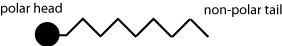
What kind of structures do you think these liquid crystals would form when mixed with water? How would this differ if they were mixed with a solvent such as hexane?
-
The disclinations shown below all result in a schlieren brush visible under polarised light microscopy. For each disclination, select the brush that would be seen [Yes for Brush A or No for Brush B] (assume the two polarisers are aligned vertically and horizontally)):
Brush A Brush B 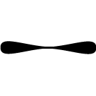
Going further
Books
- Peter J. Collings & Michael Hird, Introduction to Liquid Crystals: Chemistry and Physics, Taylor & Francis, 1997.
- Peter J. Collings, Liquid Crystals: Nature’s Delicate Phase of Matter, 2nd Edition, Princeton University Press, 2002.
Websites
- Liquid Crystal Displays paper from an MIT student
This course paper on Liquid Crystals has lots of useful information, particularly once you pass the basics which are already covered in DoITPoMS. You may also find useful information on the MIT OCW website. - Polarization of Light: circularly polarized, linearly polarized, unpolarized light (Youtube video).
The music in this video may be a little distracting and the speed a little too slow for your taste, but the video has captions and the sound is more bearable with the speed multiplier! - Introduction
to Anisotropy
A DoITPoMS TLP describing the anisotropy found in liquid crystals and other materials in further detail.
Michel-Levy Chart
Academic consultants: Richard Harrison and James Elliott (University of Cambridge)
Content development: Leila Rimmer and David Brook
Cover Image: Shanju Zhang, Ian Kinloch and Alan Windle
Web development: David Brook
Photography and video: Brian Barber and Carol Best
This DoITPoMS TLP was funded by the UK Centre for Materials Education and the Department of Materials Science and Metallurgy, University of Cambridge.
Additional support for the development of this TLP came from the Worshipful Company of Armourers and Brasiers'