Recycling of Metals (all content)
Note: DoITPoMS Teaching and Learning Packages are intended to be used interactively at a computer! This print-friendly version of the TLP is provided for convenience, but does not display all the content of the TLP. For example, any video clips and answers to questions are missing. The formatting (page breaks, etc) of the printed version is unpredictable and highly dependent on your browser.
Contents
Main pages
Additional pages
Aims
The aims of this package are as follows:
- To gain an understanding of why recycling is used and useful in today’s economy.
- To explore the huge diversity of ways in which materials science contributes to the process of recycling, relating key concepts to applications within this area.
- To engage and promote an interest in the progress and the potential for expansion in this vital area.
Before you start
- Ideally you should be familiar with the scientific concepts of:
- Phase diagrams - see the Phase Diagrams TLP
- Pourbaix diagrams - see the Nernst Equation and Pourbaix Diagrams TLP or the Pourbaix diagrams page within this TLP
- Ellingham diagrams - see the Ellingham Diagrams TLP
- Electrochemistry - see the Nernst Equation and Pourbaix Diagrams TLP for an introduction
- Materials Thermodynamics and Kinetics
- It is possible to learn from this package without this knowledge, although it is primarily aimed at linking fundamental materials science concepts with the recycling process.
Introduction
Metals have been used for thousands of years. Until the industrial revolution most metal products were recycled, because they were scarce. During the Industrial Revolution recycling was not always a high priority in the shadow of development, as there was a seemingly unending supply of ore and fuel for processing.
In today’s world, the emphasis is shifting away from energy intensive development. This is not because scarcity is once again an issue and ores are running out, but because the energy requirements to extract and process ores into the refined state needed for the high tech industry are ever increasing. There is a drive to reduce emissions from burning hydrocarbons for energy and a decreasing oil supply. This means that recycling is again an economically and environmentally feasible option, since in most cases, the energy required for recycling of metals is much less than the energy required to refine them from ores. Recycling improves the sustainability of metal product systems, by separating resource consumption from economic growth.
It is important to note when looking at recycling statistics that the definition of “% recycled” may differ. Both
Amount recycled
Amount available for recycling
and
Amount recycled metal
Amount metal produced
could be labelled as “% recycled”, although they may have very different values. Ambiguous statistics like this illustrate how background knowledge of the science involved can be useful when assessing the subject of recycling.
What metals can be recycled?
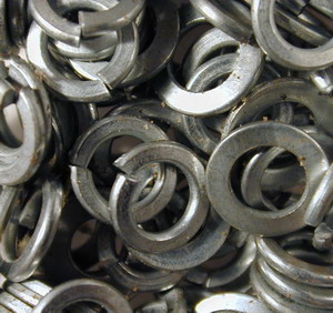
In short, almost all metals can. For example in the U.S., of the 132 million tonnes of metal ‘apparent’ supply, recycling contributed 67 million tonnes. That’s equivalent to about 50.8% [1]. In the UK, iron and steel make up the majority of the recycled metal in use. It is supplied mainly from industry and increasingly from municipal and household waste. Common examples include aluminium and tin/steel cans, and cars.
UK metals recycling statistics [2].
However, the process of metal recycling is not as simple as ‘melt it’, materials science knowledge is needed. There are two viewpoints to the recycling process, the recycling of individual metals, and the recycling of whole products.
Is recycling economically feasible?
Recycling is a great idea, in theory. The sad fact is that unless there are clear economic gains from recycling metal, large-scale initiatives are unlikely to become popular. To be economically viable, the energy saved by recycling needs to be significantly larger than the energy needed to produce the metals from ores.
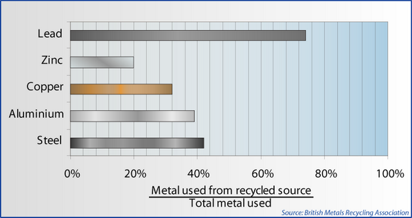
There are statistics quoted for the amount of energy saved by recycling, for example these from the British Metals Recycling Association [2]:
Metal |
Energy Saving (%) |
Steel |
62 - 74 |
Copper |
87 |
Zinc |
63 |
Lead |
60 |
But, where do these numbers come from?
It is the job of the materials scientist to come up with values like the ones above, requiring calculation as precisely as possible using fundamental background knowledge.
![]() An example of how this is done – for Aluminium.
An example of how this is done – for Aluminium.
Processing before recycling
Metals are used in a wide variety of applications. They will therefore be in a wide variety of states when they are sent for recycling.
Sorting and processing of metal scrap is essential, because when melted, mixtures of metals may become alloys. Without careful separation the quality of the final product will be reduced. This issue is explored and explained later in this TLP.
In this section, four examples of sorting and processing are investigated:–
- the Eddy current separation method (electromagnetic induction)
- the leaching and electrolysis of tin from steel cans (electrochemistry)
- the theoretical cryogenic separation of copper from steel motors (ductile-brittle transition)
- the chemical oxidation of tramp elements from molten steel scrap (Ellingham diagram)
Phase diagrams are also used to illustrate the problems that can occur when not all contaminants are removed.
Physical sorting – The Eddy current separation method
The most obvious example of sorting is that of using magnets to attract ferrous scrap. Magnetism occurs in iron due to unpaired electrons in the d-orbital giving each iron atom a magnetic moment. All these moments are aligned due to the interaction of the d-orbitals, giving an overall magnetic orientation. Magnetic materials can therefore be separated easily.
A large number of materials are not magnetic - aluminium, for example. They still need to be separated before recycling.
The eddy current separation method usually sorts this non-ferrous scrap. Eddy current separation takes the principles of electromagnetic induction in conducting materials, to separate non-ferrous metals by their different electric conductivities.
The main principle is that ‘an electrical charge is induced into a conductor by changes in magnetic flux cutting through it’. Moving permanent magnets passing a conductor generates the change in magnetic flux.
Electromagnetic induction and Eddy current generation will not be explored further here (although there are links in the Going Further section if you wish to find out more about this subject). Faraday’s law (electromagnetic) describes the generation of swirling currents in conductors, such as the non-ferrous metals in this example. Swirling currents create a magnetic field in accordance with Lenz’s law that will act to oppose the change in magnetic field being applied.
DoITPoMS standard terms of use
The basic set up is to have the non-ferrous scrap on a conveyor belt. The conveyor passes a rotating drum, inside of which is a much faster rotating magnet block (up to 4000 rpm). The magnet block causes the changing magnetic flux. Try the interactive demonstration below!
When the conducting particles move through this changing flux on the conveyor, a spiralling current and resulting magnetic field are induced. This magnetic field of the metal particles interacts with the magnetic field of the rotating drum. The interaction gives the particles kinetic energy. The scrap particles are thrown off the end of the conveyor with varying energies, causing different trajectories depending on the conductivity of the particle.
The size of the particle and the direction of rotation of the drum can be changed to vary the degree of separation. Small particles (10–50mm) can be separated owing to the degree of electrical conductivity . The most conductive materials interact the most with the magnetic field and have the longest trajectories. Aluminium has the highest conductivity for a given weight at ambient temperature than any other element. Non-metallic elements such as plastic labels and paint do not interact with the magnetic field at all. They simply fall off the end of the conveyor belt with no change in energy.
The eddy current separator is another excellent example of how knowledge of materials properties (electrical conductivity and density ) has improved recycling technology.
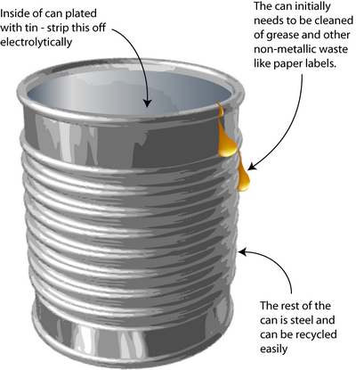
However, further processing is still needed to remove coatings and some alloys before re-melting, for example the tin coating on tin cans.
Tin can processing
Leaching and electrolysis of tin from steel cans
How do you remove the tin-plating from tin cans without dissolving the steel underneath? Solving this problem requires knowledge of the way in which metals corrode – an important concept in materials science.
The process is a little different today than explained here because the tin coating has been thinned (those who remember may have noticed the decreasing weight of ‘tin cans’ over the years).
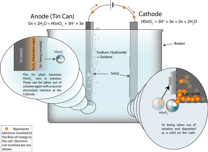
The original method to remove tin from cans was stripping by electrolysis. Knowledge of electrochemistry is critical in the designing of this process. The tin plating must be removed without dissolving the steel underneath.
![]()
The reactions used
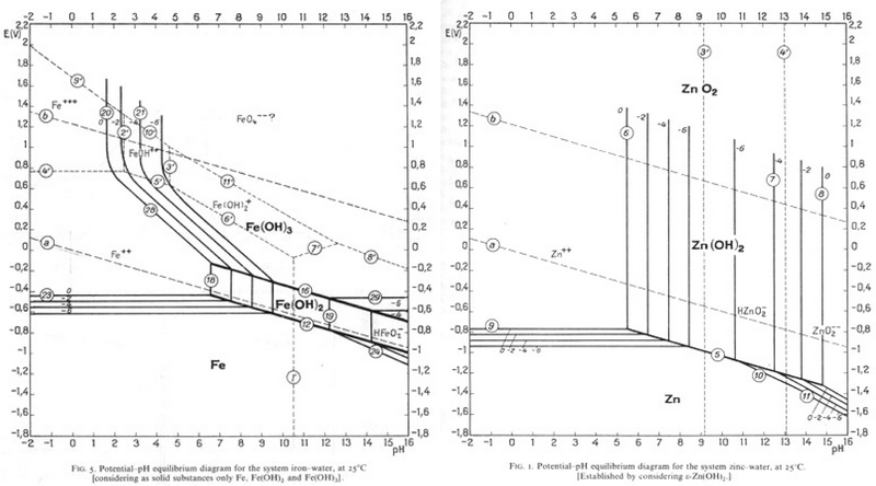
Pourbaix diagrams plot potential vs. pH. They describe the thermodynamic stability of metals that have oxidised components, as a function of the pH of the aqueous solution. Using these diagrams the most commonly used method for detinning steel has been designed.
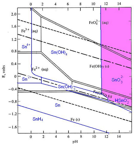
The Pourbaix diagrams for iron (black) and tin (blue) superimposed.
At a high pH (>12) – the purple region in the diagram - Sn can be stabilised in alkali solution as HSnO2– and as SnO32– in the presence of an oxidant. In this region of the diagram, iron is passivated and does not corrode. The oxidant helps this passivation to occur. In this way the tin can be removed from the surface of the can, while the steel is not harmed.
The electrochemical oxidation of the tin can be expressed as:
Sn(s) + 2H2O(l) = HSnO2– (aq) + 3H+ + 3e- (reaction 1)
Using the Nernst equation:
\[{E_{{\rm{rev}}}} = {E^0} + \frac{{RT}}{{6F}}\ln \alpha \]
We can write the electrode potential of this reaction as:
For a pH of 12 and [ HSnO2– ] of 10-2 mol, E = –0.79V. By convention this is expressed as the reduction potential, i.e. for the reverse of reaction (1). For the tin being dissolved, the potential is reverse in sign, i.e. E = +0.79V.
Under oxidising conditions, HSnO2– can be oxidised further to SnO32– :
HSnO2– + H2O = SnO32–(aq) + 3H+ + 2e- (reaction 2)
The Nernst potential for this is calculated:
\[E(V ) = 0.374 - 0.0886pH + 0.0295\log \left( {\frac{{[{\rm{SnO}}_3^{2 - }]}}{{[{\rm{HSnO}}_2^ - ]}}} \right)\]
For pH = 12 and [ SnO32– ] = [ HSnO2– ] = 10-2 mol, we find that E(v) = –0.69V.
This too is a reduction potential, i.e. for the reverse of Reaction 2. The potential for turning HSnO2– into SnO32– is +0.69V.
![]()
Setting up the process
An electrochemical detinning cell is arranged with the tin plated can as the anode. If the cell is arranged so that the reactions go backwards at a cathode plate, pure tin is deposited on the cathode.
Thus the overall cell reaction is Sn (anode)![]() Sn (cathode).
Sn (cathode).
The whole cell electrode potential is zero. The applied potential is not zero, because we need to put some energy in to overcome these energy barriers:
- Ohmic losses – the electrolyte, the connecting wires and the electrodes have electrical resistance.
- polarisation losses – the surfaces of the electrodes become charged and we need to supply the ions with enough energy to escape the charged layer.
In the same way as the aluminium cell, the whole cell electrode potential can be written as:
Ecell = Erev + ηA + ηC + (I · R)
where I is the current, R is the resistance of the components and ηA is the potential across the charged layer at the anode (and similar for the cathode).
![]()
The effect on the iron
At pH 12 and under oxidising conditions, the iron is passivated. Fe3O4 and/or Fe2O3 form an adherent, non-porous layer on the surface (a passivation layer). This slows down the rate of movement of Fe ions into solution and protects the iron from being dissolved. The presence of oxidising agents such as sodium nitrite makes the passivating layer form faster and more completely.
The passivation reaction producing Fe3O4 can be written as:
3Fe + 4H2O → Fe3O4 + 8H+ + 8e-
with a potential E0 = -0.085 - 0.0591 pH
Under oxidizing conditions, the passivating layer is Fe2O3:
2Fe3O4 + H2O → 3Fe2O3 + 2H+ + 2e-
with potential E0 =-0.221 - 0.0591 pH
At very high pH (>13), solutions can be corrosive to Fe, especially if they are free of oxidizing agents:
Fe + H2O → HFeO2– + 3H+ + 2e-
E0 = -0.2493 - 0.886 pH + 0.295 log [HFeO2-]
HFeO2– dissolves in the electrolyte and the steel can corrodes away.
The detinning process can be recreated in miniature in the laboratory:
Copper in motors
Automobiles today contain many motorised components: windows, seats, CD drives… you name it, it’s motorised. These motors contain lots of valuable copper. To take each motor apart and extract the components is not economically viable, taking into account the energy already expended in dismantling the automobile itself.
However, materials science could provide an answer:-
At low temperatures, materials become more brittle . This is because the movement of dislocations that enable plastic deformation is reduced at cold temperatures. There is a difference in the crystal structures of copper and the other components of the motor (steel and polymers). Copper has a face-centred-cubic (fcc ) structure (also known as cubic close packed), and steel has a body-centred-cubic (bcc ) structure. The fcc crystal structure has more slip systems on which dislocations can move than the bcc crystal structure. Copper can still show ductile behaviour at temperatures as low as -150°C – as shown on the graph by the high impact energy absorbed relative to other materials.
![]()
Impact energy as a function of temperature for several materials, steel, nylon and copper being motor components, showing how copper is still ductile at –150°C, but steel and nylon are not.
Separation of the copper from the rest of the components of the motor is thus possible by cooling it to -150°C and then crushing it. Screening will remove the much finer steel and plastic dusts which have formed as a result of their being much more brittle at this temperature than the copper.
It should be noted that the costs of cooling components to this temperature and then separating them do not appear to be economically feasible, as well as the fact that the steel and copper may amalgamate together and sophisticated (and therefore expensive) screening techniques would have to be employed to separate them.
However, in the recycling of Japanese home appliances, this technique is sometimes used – together with using the various ductile-brittle temperatures for non-metallic components to further aid in their pre-recycling separation.
This can be illustrated with a demonstration:
Recycling processes and issues
After it has been sorted, metal is melted in a furnace that can be of two types. The standard Basic Oxygen Furnace (BOF) and the Electric Arc Furnace (EAF). The latter is the most widely used for recycling. The image below shows the electrodes and roof of a 10 tonne electric arc furnace.
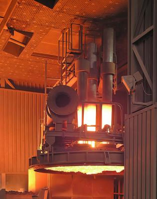
An electric arc furnace (EAF), image contributed by Haiko Hebig [6].
Steel is the most recycled metal, with 400 million tonnes per year being recycled. Most EAF based plants, called mini-mills, refine 50–250 kilotonnes of scrap per year. Some new EAF plants have the capacity to produce up to 1 million tonnes per year [3].
The electric arc furnace method is explained in detail here. When scrap is recycled, it will contain impurities that have to be removed by blowing oxygen over the molten scrap. Refining is an important step in the EAF steelmaking. Depending upon the specification of the steel made, it is important to remove impurities and alloying elements. EAF is a versatile process and can readily be operated under oxidising or reducing conditions, unlike BOF which is always operated under highly oxidising conditions.
Contaminants in aluminium alloys
Aluminium is the most widely used aerospace metal. As calculated in our example, it is highly energy intensive to produce, and recycling it is both economically and environmentally beneficial.
It is usually separated from scrap by the Eddy current separation method, as explained here. However, by chance very small amounts of ferrous metals and other contaminants will remain in the scrap when it finally reaches the melting stage.
This may not seem to be much of an issue – Aluminium is never used in the pure form. It is always alloyed with other metals and elements to give the exact mechanical and chemical properties for the desired application, and iron is almost always <1% in these alloys.
Why would having a few percent of e.g. ‘unplanned’ iron mixed in the aluminium melt be of consequence?
Look at the phase diagram below:
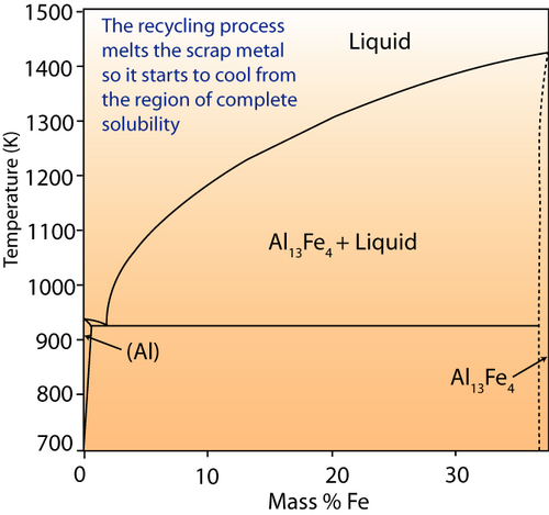
Al-Fe phase diagram.
If iron were a contaminant in aluminium melt, it would be of a small percentage. The right hand of the diagram shows the behaviour of the system at this composition. When molten, iron is completely soluble in aluminium. What do you think will happen when the ingots are cooled in terms of the microstructure?
Although the microstructure of the ingots themselves is not of particular concern, the resulting behaviour of the Aluminium in its application is. The presence of the inter-metallic compounds (such as Al13Fe4) may reduce the ductility and machineability – since the presence of precipitates will interfere with dislocation motion (precipitation hardening ) and reduce ductility.
Aluminium alloys are also heat treated to optimize their properties. Obviously, the behaviour of an aluminium alloy when annealed , for example, cannot be predicted if its composition is not precisely known.
Even though recycling aluminium is highly attractive from an economic point of view, for some high-tech applications the aluminium used has to come from primary production. Development of methods to further refine the recycled aluminium at low energy costs (to keep recycling the lower energy process compared to production) are needed if a larger amount of aluminium used in aerospace applications is to come from recycled sources.
The Ellingham diagram in removal of contaminants
The recycling of metals is a metallurgical process, and as such can be described by the rules of thermodynamics. Earlier on this was illustrated by the energy considerations of Aluminium production. On the most basic level, if the free energy of the reactants in a chemical reaction is different to that of the products, a reaction will occur. The reaction will stop when the free energies of the products and the reactants are equal. Contaminants in recycling molten metal ‘solutions’ are removed using the principles of oxidation and reduction, which can be described graphically on the Ellingham Diagram.
The Ellingham diagram shows the changes in standard free energy that occur in various reactions. In this TLP the focus is on oxidation reactions. The free energy change for oxidation reactions can be given by:
ΔG = ΔG0 − RT lnE
where K is the equilibrium constant, calculated from:
activity (metal oxide) / activity (pO2)x
where x is the number of moles of O2 in the reaction (i.e. if the reaction is Metal + 1/2O2 → MetalO, then this index = 1/2)
At equilibrium, ΔG = 0, so if ΔG = ΔG + RT lnG ΔG0 = − RT lnK.
Plotting T against ΔG0 gives the Ellingham diagram.
The oxidation Ellingham diagram is used to find the partial pressures of oxygen needed to oxidise elements at a given temperature, or reduce the metal oxide. The vertical difference between ΔG values of two lines at a specific temperature gives ΔG values used in redox reactions like the energy for primary aluminium production, explored further up in this TLP.
In the EAF, under oxidising conditions (bubbling oxygen gas through the molten metal) elements such as aluminium, silicon, manganese and chromium can be oxidised to the slag. The Ellingham diagram is used to determine the oxygen partial pressure being bubbled through the molten metal:
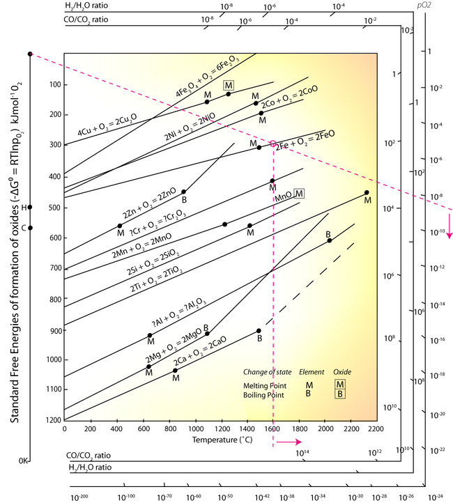
- Identify a point corresponding to a selected temperature on the line for: Fe + O → FeO, above M.
- Using this point, and the point O in the top left corner, draw a line across the diagram.
- Read the partial pressure of O2 from the right hand axis.
At any oxygen pressure higher than ~10-8.5, the iron will be oxidised at the temperature of 1600°C. It can be seen from the Ellingham diagram that the equilibrium lines of Aluminium, Silicon, Manganese and Chromium equilibrium lines are at a lower free energy position than the 2Fe + O2 → 2FeO line, and so at any partial pressure of oxygen all of these elements will be oxidised into the slag. However, Sulphur and Phosphorus cannot be removed from the steel melt by simple oxidation, other methods have to be employed.
Phosphorus oxidation is possible under very basic conditions by reducing the activity of the oxidised P2O5 in the slag, therefore altering very significantly the value of.
Sulphur can be removed also in a basic slag but under a reducing condition, by the addition of lime (desulphurization ):
FeS + CaO → CaS + FeO
For making alloy steels, it is also possible to preserve alloying elements such as Ni or Mo by using a reducing slag in the EAF.
Copper and Tin are examples of elements that cannot be refined out of steel in the EAF (or the BOF) illustrating the importance of the de-tinning process and the removal of copper from motors explored earlier in the TLP. These elements render steel very difficult to process due to hot shortness during hot rolling. It is important to control these elements at very low levels in steel. As they cannot be refined in the BOF or EAF, they will accumulate in steel and increase in successive generations. If we do not find a suitable large-scale method for removing these elements, the success of steel recycling in the future will be seriously limited. This issue is explored quantitatively in the Deeper Questions section of the TLP.
Automobile recycling
A good way to consolidate the information you have already learned in this TLP is look at how recycling processes are used in a real application, for example the recycling of automobiles. Cars are usually designed with a specific lifespan – around 10 years. This lifespan is steadily decreasing over time because of the increasing speed of development in automobile manufacture. The recycling of automobiles is a partial success story – since on average today 75% by weight of a car is recycled. Still, the amount recycled will have to increase to meet government targets. In the UK, from 2015, a target of recycling 95% by weight of a car was set. Only 10% of this weight can be fuel.
However, 75% by weight does not mean 75% by volume. A large amount of the volume of a car is in the form of plastics and other non-metallic elements such as glass. The recycled volume is almost entirely ferrous metal – virtually none of the non-metallic elements in cars are recycled. This is an issue that will have to be addressed if the new targets are to be met.
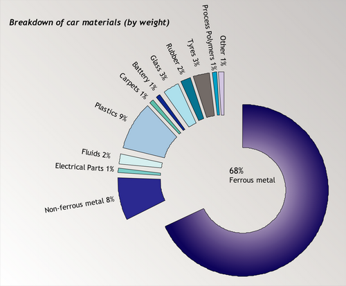
Source: ACORD annual report, 2001 [4].
There are four stages in the recycling of your average car:
- All fluids are drained from the car, including antifreeze coolant, oil, brake fluid, transmission fluid and washer fluid. In theory, distillation could be used to separate out these liquids and separate especially the oil and grease, which can be used again as fuel or lubricant.
- Easily removable parts of the vehicle are taken out and sorted according to reyclability, whether they can be re-sold (such as the bumpers), or whether they are to be landfilled. The glass windows can be recycled, along with the tyres and a few of the polymeric components.
- Crushing of the remainder of the car.
- Shredding into small particles. These particles can then be sorted by the eddy current separation method explained above, to recover the ferrous and non-ferrous metals from the residual ‘shredder fluff'.
Shredder fluff is currently landfilled, because of the economic costs of separating it out once it has been shredded into fist size pieces. Although landfilling consumes very small amounts of energy, in the UK there are new restrictions on the amount of material that is landfilled. Reasons for this are along the lines of chemicals leaching into the water supply.
Methods are continually being developed to process this residual material so that the new ELV directive can be met (95% of cars recycled from 2015) involving large amounts of research and development in the recycling of polymeric materials, again illustrating the important role materials science plays in improving the sustainability of our planet. Materials developed from biological materials that are sustainable and can be recycled are coming into use, for example, in Ford’s Model-U car.

Ford's Model-U car (Image provided by John Nens, Ford Motor Company).
The Model U is helping encourage development of materials that are safe to produce, use and recycle over and over again in a cradle-to-cradle cycle. These materials never become waste, but instead are nutrients that either feed healthy soil or the manufacturing processes without moving down the value chain.
Summary
Recycling is currently a ‘hot topic’ in the political sense, and a challenging one scientifically. As the Earth’s resources become more energy-intensive to extract, recycling will move towards the forefront of scientific research and development.
It would seem common sense that recycling is the way forward for development. Unfortunately, until the economics of recycling are more beneficial than the economics of primary production, it will not become the primary source of metal. Increased research into methods for recycling that minimise energy expenditure – and therefore increase the economic appeal of recycling - requires the expertise of materials scientists and metallurgists.
In this TLP you have:
- Learned how statistics quoted about recycling need to be critically analysed before making any conclusions.
- Used thermodynamic and electrochemical principles from materials science to actually calculate the energy saved by recycling Aluminium.
- Explored the varied methods by which metals are sorted prior to recycling from a scientific viewpoint, recognising the key role materials science plays in developing recycling technology.
- Looked at the reasons behind separating metals before remelting, using materials science concepts to explain why this is necessary.
- Learned a little about the recycling process of automobiles – acknowledging that recycling of metals in this scenario has been a success.
It was the aim of this TLP to provide a taster for the huge range of different branches of materials science that contribute to metals recycling technology.
Questions
Quick questions
You should be able to answer these questions without too much difficulty after studying this TLP. If not, then you should go through it again!
-
Ferrous scrap metal is easily separated from non-ferrous, using an electromagnet. However, non-ferrous metals still need to be separated before recycling. What materials properties allow the separation of non-ferrous metals in the eddy current separator?
-
In the eddy current separator a rotating magnet block causes a changing magnetic flux. The metal is moving through the changing flux and swirling currents are formed as a result. What effect do these swirling currents have?
-
Tin is separated from steel cans using principles involving corrosion. What method is used to decide the conditions of corrosion such that the steel will not dissolve into solution as well?
-
How is the tin removed from the solution?
-
What property of copper could be exploited in order to separate it from steel and other plastics before recycling?
Deeper questions
The following questions require some thought and reaching the answer may require you to think beyond the contents of this TLP.
-
If the calorific value of coal is 30.9 MJ kg-1 and it is combusted at 40% efficiency in a power station, how many kilograms of coal would be needed to produce 1 kg of primary production aluminium and 1 kg of recycled aluminium respectively?
Hence, or otherwise, find a percentage value for the energy saved by recycling aluminium.
-
Today, an increasing amount of metal is being galvanised. In automotives and home appliances the advantage of Galvanised Steel is that even if the Zn layer is scratched, the steel will not rust. This comes from the fact that Zn is much more reactive with O2 than Steel (Fe) and so reacts with the oxygen preferentially. However, in 5 or 6 years when these galvanised items reach the end of their lives, a huge amount of zinc-plated scrap will need to be recycled.
Zn has a boiling point of 907°C. This is a lower temperature than the melting point of steel in the EAF, so if Zn is present in the melt, it boils off and is separated. This forms a vapour. Carbon dioxide gas is also present in these exhaust fumes, and since Zn is highly reactive with oxygen, it displaces the carbon to form ZnO particles. These are in the form of an extremely fine dust that is a problem for workers at EAF plants. It can be collected, although it has to be further refined to become useful Zn (expending more energy).
Since Zn is most commonly electroplated to steel, it could be removed in the same way as tin is removed from steel, and this process is currently being researched. Find a pH and an E° value that would allow Zn to be corroded and Fe to be passivated?
-
An exemplar energy calculation for the primary formation of Al is shown in the TLP. Magnesium is another metal that has to be extracted via electrolysis rather than direct reduction with carbon, since it is more ‘reactive’ than carbon.
MgCl2(l) → Mg(l) + Cl2(g)
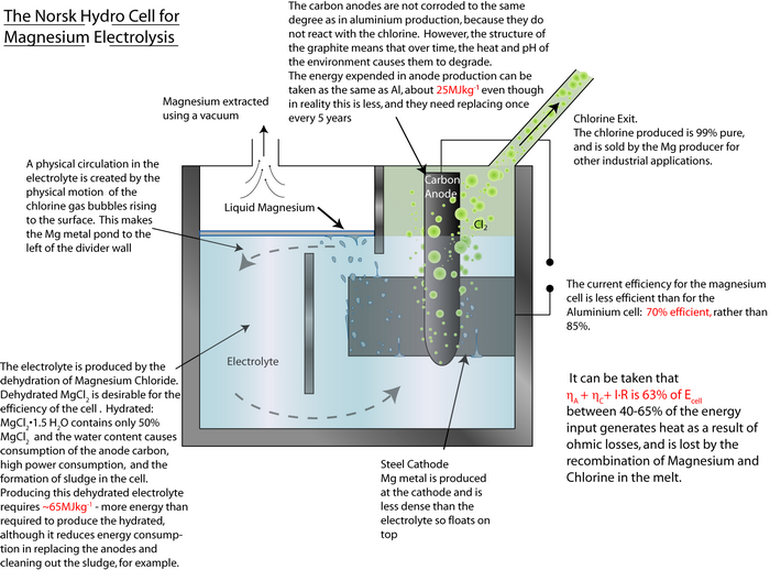
By using the same method as that used in the TLP for aluminium, calculate the energy required to produce 1 kg of magnesium.
-
In the electric arc furnace, conditions are created such that impurities resulting from poorly sorted steel scrap are reduced/oxidised into slag. It was explained in the TLP how the Ellingham diagram can be used to predict which metals will come out of solution with the steel and which ones will not. Phosphorus (P), Copper and Tin cannot come out of solution this way, and other methods have to be employed (as described) to remove them from solution.
It was explained that P is removed from the EAF by addition of CaO to produce a very basic slag.
Why does this occur?
Phosphorus can oxidise to P2O5 as shown:
The driving force for P oxidation is lower than that for the oxidation of Fe. Thermodynamically, as depicted in the Ellingham diagram, oxidation of P from Fe melt is not favourable. As the concentration of P in the melt is low, the activity of P in the Fe melt is in the order of magnitude of 10-3, further decreasing the driving force for oxidising and thus removing P from the melt.
It will be possible to remove P from the Fe melt by an oxidation reaction, provided the driving force is greatly increased by achieving a very low activity for P2O5 in the slag in equilibrium with Fe such that P2O5 is transferred from the melt to the slag. For this to happen in the slag, the ΔG value for the oxidation of Fe to FeO needs to equal the ΔG value for P to P2O5.
If we assume that Fe is pure (which is not unreasonable) and the slag is saturated with FeO, ΔG of the reaction:
becomes equal to ΔG°, because the activity term
 .
.*Note that in practice an oxidising slag actually contains 20 mol% FeO (at which the activity of FeO is ~0.2).
For P to be oxidised into the slag spontaneously, the reaction
needs to be at least equal the value of ΔG° from the iron reaction.
Since the value of ΔG° for the oxidation of P is known – it can be found from the Ellingham diagram at the temperature within the EAF, one can calculate the required activity of the P2O5 to allow it to move into the slag in the EAF. Find this value.
Going further
References
[1] USGS Minerals Yearbook, 2003.
[2] British Metals Recycling Association.
[3] Part III Materials Science Lecture notes © Dr R.V. Kumar, University of Cambridge.
[4] WasteOnline website (no longer online).
[5] Part IA Materials Science Lecture notes © Dr J.L. Driscoll, University of Cambridge.
[6] Personal weblog of Haiko Hebig.
[7] Atlas of Electrochemical Equilibria in Aqueous Solutions, Pourbaix.
Websites
- An excellent website on aluminium can recycling, with information on starting
recycling initiatives in your area:
http://www.alupro.org.uk/
- More information on electromagnetic induction
http://en.wikipedia.org/wiki/Electromagnetic_induction
- More information on eddy current generation
http://en.wikipedia.org/wiki/Eddy_currents
Pourbaix diagrams and how they work
An electrochemical cell contains reactions as follows:
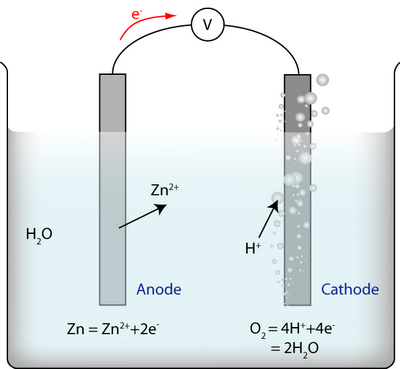
There are three reactions:
- The reaction at the anode between metal ions and electrons
- The reaction at the cathode between water and electrons
- The reaction of the whole cell, i.e. the two half-cell reactions added together: \(2{\rm{Zn}} + {{\rm{O}}_2} + 4{{\rm{H}}^ + } = 2{\rm{Z}}{{\rm{n}}^{2 + }} + 2{{\rm{H}}_{\rm{2}}}{\rm{O}}\)
For each of these reactions it is true that:
$$\Delta G = \Delta {G^o} - RT\ln \left( {{{\prod\limits_X {a_X^{{n_X}}} } \over {\prod\limits_Y {a_Y^{{n_Y}}} }}} \right)$$
where:
ΔG is the free energy change of the reaction.
ΔG0 is what the free energy change would be if every component were in its standard state.
ax is the activity of reaction product X and is the activity of reactant Y.
nx is the stoichiometric coefficient of reaction product X, and likewise for the reactants.(The stoichiometric coefficient is the number of that molecule that are involved in the reaction; for the whole-cell reaction written above, the stoichiometric coefficient of water is 2, and of oxygen gas is 1.)
R is the ideal gas constant and T is the temperature.
The symbol \(\Pi \) is the multiplying equivalent of \(\Sigma \) – all the terms after it are multiplied together.
![]()
Equilibrium
If a reaction is at equilibrium, \(\Delta G = 0\), and the free energy G of the system is at a minimum with respect to how much of the reactants have been converted to products. When this is the case, we obtain:
$$\left( {{{\prod\limits_X {a_X^{{n_X}}} } \over {\prod\limits_Y {a_Y^{{n_Y}}} }}} \right) = K$$
where K is the equilibrium constant.
Thus we can deduce that \(\Delta {G^o} = RT\ln K\); this is true of a reaction whether it is at equilibrium or not. (ΔG0 for a reaction is determined by the energies of the bonds within the molecules of the reactants and products, and this is independent of how many such molecules there are per unit volume.)
![]()
The cathode reaction is at equilibrium if there is no power supply connected to the circuit. It can do this because each atom or ion has enough energy to undergo the reaction in either direction; there is nothing stopping it being at equilibrium. The anode reaction is also at its own equilibrium.
The reaction for the whole cell is not at equilibrium. There is too much of an energy barrier for it to be able to get there – the ions have to diffuse through the electrolyte and the electrons have to go round the wires. (Or through a high impedance voltmeter, which they almost certainly cannot do.)
Thus for the example given
$$\Delta G = \Delta {G^o} - RT\ln \left( {{{{a_{Z{n^{2 + }}}}a_{H + }^2p_{{O_2}}^{{\raise0.7ex\hbox{$1$} \!\mathord{\left/ {\vphantom {1 2}}\right.\kern-0em} \!\lower0.7ex\hbox{$2$}}}} \over {{a_{Zn}}{a_{{H_2}O}}}}} \right)$$
ΔG0 ≠ 0 and the quotient is not the equilibrium constant.
We can convert this into an expression in electrical potentials using the general rule:
$$\Delta G = - zFE$$
where z is the stoichiometric number of electrons in the reaction. (This is due to Faraday’s law, of which more is given here.)
In this form we have the Nernst equation for the cell:
$${E_e} = {E^o} - {{RT} \over {zF}}\ln \left( {{{{a_{Z{n^{2 + }}}}a_{{H^ + }}^2p_{{O_2}}^{{\raise0.7ex\hbox{$1$} \!\mathord{\left/ {\vphantom {1 2}}\right.\kern-0em} \!\lower0.7ex\hbox{$2$}}}} \over {{a_{Zn}}{a_{{H_2}O}}}}} \right)$$
The activities of Zn and water are one, because Zn is in its standard state and the water is so much more abundant than its solutes that it may as well be in its standard state. Thus:
$${E_e} = {E^o} - {{RT} \over {zF}}\ln \left( {{a_{Z{n^{2 + }}}}a_{H + }^2p_{{O_2}}^{{\raise0.7ex\hbox{$1$} \!\mathord{\left/ {\vphantom {1 2}}\right.\kern-0em} \!\lower0.7ex\hbox{$2$}}}} \right)$$
Ee is the equilibrium potential – it is the potential of the whole cell when the electrodes are at equilibrium within themselves.
It can be worked out (easily, using algebra with a pen and pencil) that
$${E^o} = {{RT} \over {zF}}\ln K$$
where K is the equilibrium constant – i.e. if we were at equilibrium over the whole electrochemical cell, then E would be zero. E0 is a property of the system like ΔG0, and is still equal to the same number even when the whole cell is not at equilibrium. If for some reason it was required to find the value of E0, we could use this expression. E0 is called the standard electrode potential.
The Relevance of pH
The Nernst equation shows that the equilibrium potential is affected by the activity of hydrogen ions in the electrolyte. This means that the electrode potential must depend on the pH of the electrolyte. This can easily be found by using the relation:
$$pH = - \log \left[ {{{\rm{H}}^{\rm{ + }}}} \right]$$
Square brackets denote “concentration of \({{\rm{H}}^{\rm{ + }}}\)”. To make the Nernst equation in terms of concentrations so we can get it in terms of pH, we can express the quotient from the start in terms of concentrations and partial pressures instead of activities and partial pressures. (This implies that all the solutes in the electrolyte have the same relation between concentration and activity. That is not quite true but it is an adequate approximation in this case.)
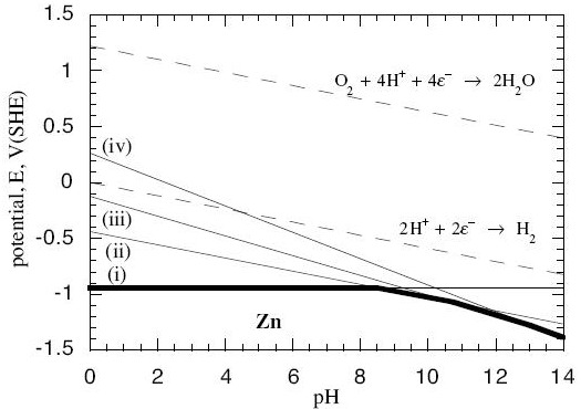
Now, in every system, there is more than one possible reaction between the metal and its oxides and hydroxides, and the water. In the zinc system, for example, we have these possible reactions:
$$\eqalign{ & {\rm{Z}}{{\rm{n}}^{2 + }} + 2{e^ - } = {\rm{Zn \hspace{9.8em}(reaction\; i)}} \cr & {\rm{Zn(OH}}{{\rm{)}}_{\rm{2}}} + 2{{\rm{H}}^{\rm{ + }}} + 2{{\rm{e}}^{\rm{ - }}}{\rm{ }} = {\rm{ Zn}} + 2{{\rm{H}}_{\rm{2}}}{\rm{O \hspace{1.2em} (reaction\; ii)}} \cr & {\rm{HZn}}{{\rm{O}}_{\rm{2}}}^{\rm{ - }} + 3{{\rm{H}}^{\rm{ + }}} + 2{{\rm{e}}^{\rm{ - }}} = {\rm{Zn}} + 2{{\rm{H}}_{\rm{2}}}{\rm{O \hspace{1.4em} (reaction\; iii)}} \cr & {\rm{Zn}}{{\rm{O}}_{\rm{2}}}^{{\rm{2 - }}} + 4{{\rm{H}}^{\rm{ + }}} + 2{{\rm{e}}^{\rm{ - }}} = {\rm{Zn}} + 2{{\rm{H}}_{\rm{2}}}{\rm{O \hspace{1.7em} (reaction \;iv)}} \cr} $$
When we do the calculations, we find the Nernst equations for these reactions are:
$$\eqalign{ & {\rm{For\; reaction \;i: }}{E_e} = - 0.763 + 0.0295\log \left[ {Z{n^{2 + }}} \right] \cr & {\rm{For\; reaction\; ii: }}{E_e} = - 0.439 - 0.0591pH \cr & {\rm{For\; reaction\; iii: }}{E_e} = 0.054 - 0.0886pH + 0.0295\log \left[ {HZn{O_2}^ - } \right] \cr & {\rm{For\; reaction\; iv: }}{E_e} = 0.441 - 0.1182pH + 0.0295\log \left[ {Zn{O_2}^{2 - }} \right] \cr} $$
Now we can plot these as lines on a graph with pH on the horizontal axis and Ee on the vertical axis:
 (Contributed by G.T. Burstein, University of Cambridge.)
- The solid lines are the lines at which the anode reactions (i – iv) are at equilibrium within themselves. Off the lines, they are not at equilibrium.
- The dotted lines are equilibrium lines for reactions that water can undergo with oxygen and hydrogen, independently of the zinc.
- Below the bold line, all the reactions with Zn metal in them are pushed off equilibrium towards there being more solid Zn and less of the dissolved reactants on the other side of the reaction. No corrosion occurs below the bold line because it would be energetically unfavourable.
Aluminium production: an example calculation of the energy saved by recycling
To find how much energy is saved by recycling aluminium, the amount of energy expended in primary production has to be calculated. When this is known, it can be compared with the energy expended to recycle the same amount of aluminium. 1 kg is a standard mass that will be used in this calculation to compare the two energy values.
![]()
Primary Production of Aluminium
The Bayer - Hall-Héroult process produces primary aluminium from bauxite ore. Initially, the Bayer process produces pure alumina (Al2O3) by dissolving the raw bauxite ore in aqueous alkali solution. This is carried out at high pressure and temperature. Pure Al(OH)3 is precipitated from the resulting solution, which allows separation of insoluble impurities. It is then calcined to pure alumina.
Next, the Hall-Héroult process involves an electrochemical cell and pure Al2O3 as the feed material. It is dissolved in a molten Cryolite electrolyte (Na3AlF6 – itself modified by the addition of AlF3, CaF2 and others) which brings the melting temperature to 950–1000°C. The addition of the cryolite therefore saves energy.
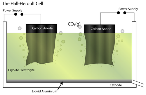
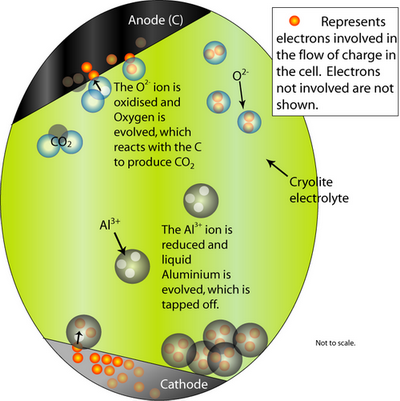
At the cathode, the Al2O3 is reduced to molten Al. At the anode, oxygen from the alumina reacts with the C electrode to form CO2(g).
The overall cell reaction is written as:
Al2O3(l) + 3/2 C → 2Al (l) + 3/2 CO2 (g)
ΔG (1273K) = 686 kJ at ~975°C
(ΔG for this reaction can be found using the Ellingham diagram.)
The minimum reversible standard potential E0 is given by:
$${E^o} = - {{\Delta {G^o}} \over {6F}}$$ , where G is the Faraday’s constant.
$${E^o} = {{{\rm{686000}}} \over {{\rm{6}} \times {\rm{96500}}}} = - {\rm{1}}{\rm{.18 V}}$$
As the Al2O3 is decomposed, it will decrease in concentration in the cryolite solution. This will cause the activity of the Alumina (\({a_{A{l_2}{O_3}}}\)) to decrease until saturation of the solution with Al2O3 is restored. The decrease in the value of \({a_{A{l_2}{O_3}}}\) affects the reversible potential (causes it to increase in magnitude from the standard potential) because of the Nernst equation (the derivation of which is given here [5]).
$${E_{rev}} = {{RT} \over {6F}}\ln {a_{A{l_2}{O_3}}}$$
The symbol Erev represents the minimum potential required that has to be overcome to start producing any Al at the cathode. The actual potential required is much higher than just the value of Erev, due to factors such as polarisation and Ohmic losses. So, the final potential required for the Hall-Héroult cell (Ecell) is given by:
$${E_{cell}} = \left| {{E_{rev}}} \right| + {\eta _A} + {\eta _C} + I \cdot R$$
where the symbols ηA and ηC refer to overpotentials at the anode (A) and cathode (C), respectively. Typically, ηA ≈ 0.5V and ηC ≈ 0.5V. I·R is the Ohmic loss. Most of the resistance, R, (>80%) in this value arises in the molten electrolyte. I·R ≈ 2.5 V at a typical current density of I ≈ 1 A cm-2 and a capacity rating of 100 kA. (These cells are designed to operate in the range 50–250 kA.)
Under the above conditions, Ecell ≈ 5V.
Now the energy can be found by first applying Faraday’s law (The mass of an element discharged at an electrode is directly proportional to the amount of electrical charge Q passed through the electrode) to the value of Ecell to calculate the amount of charge (Q) that is required to produce 1 kg of Aluminium:
$$Q = {{3F} \over {\left( {{{{M_{Al}}} \over {1kg \times {{10}^3}g{\rm{ }}k{g^{ - 1}}}}} \right)}} = {{3 \times 96540} \over {\left( {{{27} \over {{{10}^3}}}} \right)}} = 10.73 \times {10^6}{\rm{C}}$$
where \({M_{Al}}\) is the molecular weight.
Since E = QV, the electrical energy consumed for producing 1 kg of Al:
≈ Q × Ecell = (10.73 × 10⁶)∙5 ≈ 50 MJ
The value calculated above assumes that there is 100% current efficiency. In fact, the current efficiency is usually 85-95%. The energy required increases as a result to ≈ 55 MJ kg-1. It should be noted that hydroelectric power is 90% efficient, and some aluminium plants have been preferentially located adjacent to these hydroelectric plants.
However, the electrical energy is normally produced by burning fossil fuels that are only 30-40% efficient. The real energy expended in this procedure therefore is given by:
$${{55 \times {{10}^6}} \over {0.35}} \approx 160\; -\; 170\;{\rm{ MJ k}}{{\rm{g}}^{{\rm{ - 1}}}}$$
The energy consumed in the Hall-Héroult process is then added to the other energy-consuming parts of the Al-production process to find a value for the amount of energy used to produce 1 kg of aluminium from ore:-
- Energy required for the Hall-Héroult process ≈ 165 MJ kg-1
- Energy required in producing C anode: ≈ 25 MJ kg-1
- Energy required in producing the electrolyte: ≈ 5–10 MJ kg-1
- Energy expended in the Bayer Process to produce Al2O3 ≈ 60 MJ kg-1
Therefore, the total energy ≈ 260 MJ kg-1
Currently, every year, the world uses 20 million tonnes of aluminium. This means that more than 200 million tonnes of coal (or the energy equivalent of an energy-producing fuel e.g. gas or oil) is required in power plants each year [3]. That is a huge amount of energy. In fact, it is the same amount as 300–500 cities consume in a year!
The energy invested in primary Aluminium production is preserved in the metal. Used aluminium products can be melted down into new Aluminium repeatedly, although this process is not without complications, as are explained later in this learning package. To find out how much energy is saved by recycling aluminium, the total energy for primary aluminium production needs to be compared with the energy required to produce the same amount of aluminium by recycling.
![]()
Recycling Aluminium
Most of the energy required in the recycling of aluminium comes from the heating, and can be calculated by adding:-
$$\int\limits_{298}^{933} {{C_P}} (Al(s))dT$$ (Energy to heat the aluminium from room temperature to the melting point)
+ $$\Delta H_{933}^0(m)$$ (energy required for latent heat of melting)
+ $$\int\limits_{933}^{1000} {{C_P}(Al(l))dT} $$ (energy required to heat up molten aluminium to the casting temperature)
$$ = \int\limits_{298}^{933} {{C_P}} (Al(s))dT + \Delta H_{933}^0(m) + \int\limits_{933}^{1000} {{C_P}(Al(l))dT} $$
where:
$${C_P}(Al(s)) = 20.67 + 12.38 \times {10^{ - 3}}{\rm{ TJ mo}}{{\rm{l}}^{{\rm{ - 1}}}}$$
$$\Delta H_{933}^0(m) = 10.7{\rm{ kJ mo}}{{\rm{l}}^{{\rm{ - 1}}}}$$
$${C_P}(Al(l)) \approx 25.3{\rm{ kJ mo}}{{\rm{l}}^{{\rm{ - 1}}}}$$
Molecular mass of Aluminium = 27 g mol-1
Thus, in $$1{\rm{ kg}} = {{1000} \over {27}} = 37.037{\rm{ mol k}}{{\rm{g}}^{{\rm{ - 1}}}}$$
From these data the energy required (assuming an efficiency of 60-80%) can be calculated at approximately 6–10 MJ kg-1 (The proof is left to the reader![]() ).
).
Therefore even with the excess energy required to process the aluminium before it is re-melted, the energy expended is very significantly lower than creating new metal from ore:
260 MJ kg-1 >> 6–10 MJ kg-1
Some energy, it should be noted, is used in the sorting and processing of the metal scrap. ‘Processing’ including de-coating of the lacquer layers and shredding before it reaches the melting stage. Energy is also used in the transport of the scrap to the recycling plant, which may evoke concerns about the emissions from vehicular transport. Nevertheless, if these emissions are compared with the emissions from the power stations producing the electricity for the primary process they become negligible.
If recycling is an economically sound process – how does materials science contribute to the industrial methods used to recycle metals?
Academic consultant: Vasant Kumar (University of Cambridge)
Content development: Kathy Mather
Web development: Jin Chong Tan
This DoITPoMS TLP was funded by the UK Centre for Materials Education and the Department of Materials Science and Metallurgy, University of Cambridge.