The bi-material strip
When a component made up of two different materials bonded together is heated or cooled, a misfit is generated between the new dimensions each would adopt if they were isolated. This mismatch can set up stresses and associated distortions. On the other hand, the effect can be exploited by using such a couple to detect or measure temperature changes. An example of such a sensor is the simple bimetallic strip, which has long been used in thermostats and other thermal devices.
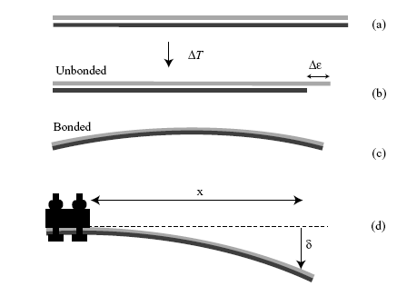
As shown in the following diagram, if unbonded the free lengths of each material would be different after a temperature change. When bonded, however, the difference in unconstrained lengths gives rise to internal stresses within the strip, causing it to bend.

The bimaterial strip: (a) Two strips of equal initial length undergo (b) a temperature change ΔT, such that the relative difference in their unconstrained lengths is Δε(= Δα ΔT). (c) Since the two strips are in fact bonded together, the resulting internal stresses generate a uniform curvature. (d) Clamping a bimaterial strip, to allow measurement of the deflection and hence the curvature.
When thermal equilibrium is reached, the resulting curvature, κ, (reciprocal of the radius of curvature) is related to the displacement, >δ, and the distance, x, along the strip at which the displacement is being measured by the relationship
|
\[\kappa = \frac{{2\sin \left[ {{{\tan }^{ - 1}}\left( {{\delta }/{x}} \right)} \right]}}{{\sqrt {\left( {{x^2} + {\delta ^2}} \right)} }}\] |
(3)
|
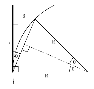
This can be derived using the geometrical construction shown below.

Geometry for derivation of equation (3)
\[\kappa = \frac{{2\sin \theta }}{{\sqrt {\left( {{x^2} + {\delta ^2}} \right)} }}\]
i.e.
\[\kappa = \frac{{2\sin \left[ {{{\tan }^{ - 1}}\left( {\delta }/{x} \right)} \right]}}{{\sqrt {\left( {{x^2} + {\delta ^2}} \right)} }}\]
The curvature is also related to the material properties and dimensions through the equation
|
\[\kappa = \frac{{6{E_A}{E_B}\left( {{h_A} + {h_B}} \right){h_A}{h_B}\Delta \varepsilon }}{{{E_A}^2{h_A}^4 + 4{E_A}{E_B}{h_A}^3{h_B} + 6{E_A}{E_B}{h_A}^2{h_B}^2 + 4{E_A}{E_B}{h_A}{h_B}^3 + {E_B}^2{h_B}^4}}\] |
(4)
|
where EA, EB are the Young's Moduli, and hA, hB the thicknesses of the two materials A and B. The misfit strain, Δε, is given by
|
Δε = (αA - αB) ΔT |
(5)
|
where αA and αB are the thermal expansivities of the constituents. Derivation of equation (4) is not particularly complex, but need not concern us (see Clyne T W, Key Engineering Materials, vol.116/117 (1996) p.307-330). It is based on the balancing of the bending moment generated by the misfit strain against the opposing moment offered by the beam.
It can be seen that the curvature depends, not just on the expansivity mismatch and temperature change, but also on the relative stiffness and thickness of the two materials. If the two strips are of equal thickness (h), and the stiffness ratio is termed E*, the equation can be re-written
|
\[\kappa = \frac{{12 \Delta \varepsilon }}{{{h_{}}\left( {{E_*} + 14 + 1 / {E_*}} \right)}}\] |
(6)
|
It can be seen that there is a scale effect - i.e. the curvature will be greater when the strips are thinner. Furthermore, a glance at the denominator shows that the curvature will be small if one of the materials has a much greater stiffness than the other.
Assuming the α values for steel and aluminium given in the properties table to be correct, it is possible to use eqns. (3), (5) and (6) to estimate the value of ΔT corresponding to a measured curvature of the steel - Al strip and hence estimate the boiling temperature of liquid nitrogen.

