Micrograph Library
Browse the libraryAdvanced searchSystemsCompositionsTechniquesKeywordsPhase diagramsHelpPreferencesAbout the micrograph libraryTerms of useContribute micrographs!FeedbackLinksCredits Print this page
Full Record for Micrograph 620
[124 KB]
View micrograph
.. in new window
View micrograph and record
.. in new window
You can also view and download the micrographs on Flickr
- Micrograph no
- 620
- Brief description
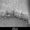
- Kevlar fibre composite fracture surface
- Keywords
- alignment, composite material
 , epoxy , fibre , fibrillation , fracture , hackle region , Kevlar , liquid crystalline polymer (LCP), lyotropic, polymer , polymer composite, reinforcement , shear
 - Categories
- Composite, Fracture, Polymer, Polymer composite
- System
- Kevlar composite
- Composition
- Kevlar fibre, epoxy resin matrix
- Standard codes
- Reaction
- Kevlar is a lyotropic liquid crystal polymer. This means that it can be readily processed in solution (in this case, sulphuric acid). It is annealed under tension to increase its elastic modulus
- Processing
- A crude Kevlar composite was made by laying out 40 tows of fibre, painting them with epoxy resin, compressing them in a mould, and curing them for five hours at 100-190 degrees C
- Applications
- Kevlar composites are used as a structural material in the aerospace and automotive industries, as well as in certain high-performance sporting equipment. They present exceptional stiffness and can be structurally optimised for particular load-bearing applications.
- Sample preparation
- The bar has been bent to failure in a three-point bending rig.
- Technique
- Scanning electron microscopy (SEM)
- Length bar
- 600 μm
- Further information
- Because a relatively short beam was used, significant shear stresses existed in the beam, and failure has occurred principally by shear. In this mode, the specimen splits longitudinally along planes parallel to its neutral axis, due to shear failure within the matrix and at the weak interface between fibres and matrix. Matrix porosity (and particularly the long longitudinal voids present in this specimen), the poor wetting of fibres by the resin, and poor fibre distribution will all promote failure by shear. However, it may be that this failure mechanism has been partly inhibited by poor fibre alignment since some off-axis fibres will reinforce the matrix in shear
- Contributor
- J A Curran
- Organisation
- Department of Materials Science and Metallurgy, University of Cambridge
- Date
- 03/10/02
- Licence for re-use
 Attribution-NonCommercial-ShareAlike 4.0 International
- Related micrographs