Re-use of this resource is governed by a Creative Commons
Attribution-
NonCommercial-ShareAlike 4.0 International
https://creativecommons.org/licenses/by-nc-sa/4.0/
NonCommercial-ShareAlike 4.0 International
https://creativecommons.org/licenses/by-nc-sa/4.0/
Example Manufactured Article
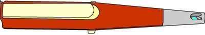
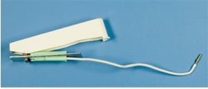
This is a piezoelectric lighter. It creates sparks which
are used to light gas burners. When the button is depressed a spark
can be seen between the electrode and the point of the cap.
Click to depress the button
Click the start button to begin dismantling the article
Click on the components to dismantle the article

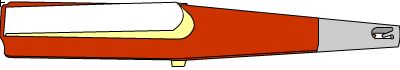
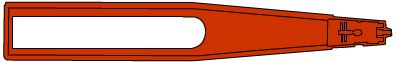
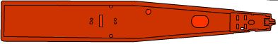
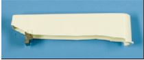
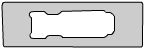
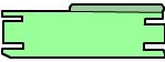
The outer case top and bottom pieces were glued together.
They are obviously both made of the same material, so it is unnecessary
to try to characterise them both individually. They must be heat resistant,
tough, non toxic and easy to clean to suit the environment.
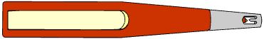
This component has strong colour and is very light; it is a polymer. The next step is to take a small sample and perform the polymer tests.
This component has strong colour and is very light; it is a polymer. The next step is to take a small sample and perform the polymer tests.
Does it melt? Yes Is it self-extinguishing? No
Does it float? Yes Is it transparent? No
Does it burn? Yes Does it produce black smuts
Does it drip? NO and smell of rubber? Yes
Does it float? Yes Is it transparent? No
Does it burn? Yes Does it produce black smuts
Does it drip? NO and smell of rubber? Yes
The polymer tests suggest ABS, but the results can
be affected by the addition of dyes etc (especially the question about
transparency.)
(see the Polymer Identification Table)
These tests may not be conclusive, and so it may be advisable to take an IR spectrum of the polymer.
(see the Polymer Identification Table)
These tests may not be conclusive, and so it may be advisable to take an IR spectrum of the polymer.
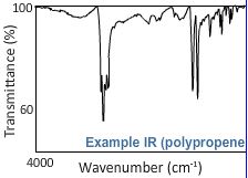
An IR spectrum can be interpreted by looking at the
peak values or by matching the general shape.
The IR spectrum revealed the presence of three different
monomers. This may mean the polymer is a blend, but in this case the
monomers were acrylonitrile, butadiene and styrene. These are the components
of the common terpolymer ABS (Acrylonitrile-butadiene-styrene).
ABS satisfies the requirements well, having high toughness and being easily coloured.
ABS satisfies the requirements well, having high toughness and being easily coloured.
Click on the components to dismantle the article
Click on the components to dismantle the article
Click on the components to dismantle the article
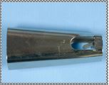
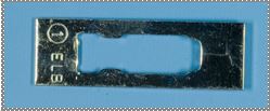
The lighter cap has a shiny metallic appearance and
it is attracted to a magnet. We know from its function that it must
have reasonably good mechanical properties (so it does not deform if
dropped on the floor for example), it must conduct electricity (for
the spark gap interface), it cannot corrode easily and must be aesthetically
pleasing. This strongly suggests an iron alloy.
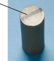
Grain boundaries meet at approximately 120° (stable
triple junctions)
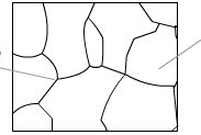
Equiaxial grains - ferrite
After identifying the class the next step is to take
a sample and prepare it for optical microscopy.
The micrograph shows fairly uniform, equiaxed grains, a schematic is shown above.
Remember it is important to add labels and scales to all micrographs and sketches.
The micrograph shows fairly uniform, equiaxed grains, a schematic is shown above.
Remember it is important to add labels and scales to all micrographs and sketches.
The point inside the cap is part of the spark circuit.
The spark jumps between this and the electrode.
The combination of what we know about the requirements
of the material and what we see in the micrograph leads to the conclusion
that this is a low C steel. The properties required might also suggest
the use of stainless steel, but stainless steel is much more expensive
than low C steel.
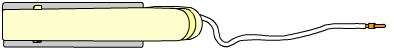
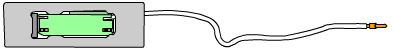
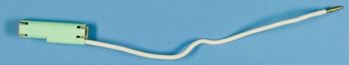
This wire connects the button mechanism to the cap,
making up an important part of the spark circuit. The end of the wire
is hooked through a hole in the bottom of the case. This is a metal
and by the colour it is obviously copper. It must be ductile and highly
conductive, and copper fulfils these requirements. This component will
also not be subjected to much wear as it sits in the bottom of the case.
It was probably made by extrusion or drawing.
The button is also made of ABS (the polymer tests and
IR were the same as for the case).
When the button is depressed a hinge piece rocks, putting pressure on the part of the mechanism housing the piezoelectric.
When the button is depressed a hinge piece rocks, putting pressure on the part of the mechanism housing the piezoelectric.
Click on the components to dismantle the article
This component forms part of the spark circuit. It
comes into contact with a wire in the bottom of the lighter case. This
means it must be conducting and rigid because it also provides a frame
for the piezoelectrics. The material is magnetic and difficult to cut;
the micrograph reveals this is low C steel (the same as the cap).
Click on the components to dismantle the article
Click on the components to dismantle the article
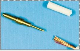
This wire connects the piezoelectric to the electrode,
making up part of the spark circuit. It is made up of a bundle of wires
with an insulating coating. By the colour (and function) we can tell
the wires are copper.
The polymer tests suggest ABS, but the results can
be affected by the addition of dyes etc (especially the question about
transparency). (see the Polymer Identification Table)
These tests may not be conclusive, and so it may be advisable to take an IR spectrum of the polymer.
These tests may not be conclusive, and so it may be advisable to take an IR spectrum of the polymer.
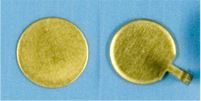
This component is one side of the spark gap interface.
It must be a good conductor. From the colour this component is a brass
(Cu-Zn alloy). Copper has a very high conductivity, without being too
expensive, and the addition of zinc improves the mechanical properties
of the component. Looking at a metallographic sample can allow estimates
of the actual composition as well as giving information on possible
manufacturing techniques.
The micrograph reveals a two phase metal with some
dark inclusions within grains and at grain boundaries. This is lead
which is often added to brass to improve machinability. There is also
clear directionality along the long axis of the component. This suggests
it has been extruded and then machined to give the final shape.
Does it melt? Yes
Does it float? Tes
Is it a foam plastic? No
Can it be scratched by a fingernail? No
Does it float? Tes
Is it a foam plastic? No
Can it be scratched by a fingernail? No
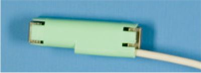
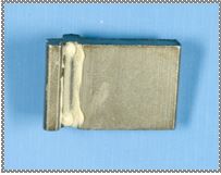
This component houses the piezoelectric unit and holds
it in place. It is not directly stressed, but must be relatively strong
to support and protect the piezoelectrics. It must also be insulating
- to avoid short circuits. This piece, as we can tell by the low density
and bright colour, is a polymer. The polymer tests suggest that this
is polypropene, which is also backed up by the IR spectrum. This is
an appropriate material because it has good mechanical properties and
is also cheaper than ABS (the other polymer in this article).
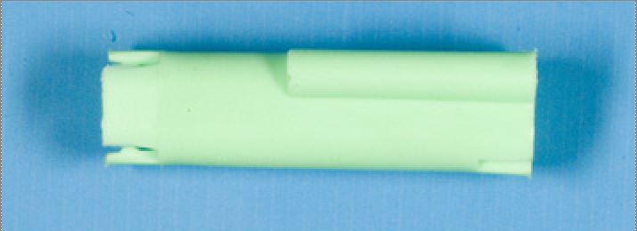
This component does not show obvious injection points
(as many of the other polymer components do), but some mould lines are
visible and injection moudling is by far the most likely method of processing.
Injection moulding is cheap and has a very fast cycle time. It also
gives an accurate shape, which is required for holding the piezoelectric
unit in the right place.
Click on the components to dismantle the article

This component is the rocking hinge, when the button
is depressed it causes this to tilt, compressing the piezoelectrics.
The photo above shows some lubricant used to allow the part to move
easily.
It is magnetic and must be quite strong and hard.
It is magnetic and must be quite strong and hard.
The micrograph shows lenticular microstructure aligned
in certain directions. This shows the component is a martensitic steel;
the lenticular shape minimises strain energy. This component is made
of a very hard form of steel.
The micrograph also reveals some porosity suggesting the component was cast.
The micrograph also reveals some porosity suggesting the component was cast.
Click on the components to dismantle the article
This component must be able to withstand and apply
force to the piezo, it also forms part of the spark circuit and so must
be conducting. Micrographs show this is also martensitic steel (same
as the hinge piece). The microstructure at the edges is finer and there
is visible porosity. Such a small component is unlikely to have been
cast. More probably it was fabricated using a powder route, involving
sintering at high temperature.
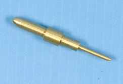
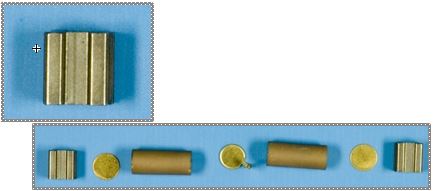
These components form the contacts between the piezoelectrics
and the rest of the circuit. The point on the middle contact is inserted
into the end of the coated wire, which goes to the brass electrode.
By the colour we can tell these are also brass, the microstructure shows annealing twins, suggesting they underwent heat treatment. Annealing would improve both mechanical and electrical properties.
By the colour we can tell these are also brass, the microstructure shows annealing twins, suggesting they underwent heat treatment. Annealing would improve both mechanical and electrical properties.
The black line (found on both piezo electrics) is a
non conducting marker to ensure they are the correct way around.
These components are the piezoelectrics. (see the
TLP on Piezoelectric
materials)
Mounting this and taking an EDS shows it contains 55% lead, 11% zirconium, 6% titanium, 22% oxygen, 6% tin. This suggests PZT (Lead-Zirconium-Titanium-Oxide). The porosity visible in the mounted sample suggests this was sintered.
Mounting this and taking an EDS shows it contains 55% lead, 11% zirconium, 6% titanium, 22% oxygen, 6% tin. This suggests PZT (Lead-Zirconium-Titanium-Oxide). The porosity visible in the mounted sample suggests this was sintered.
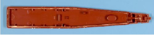
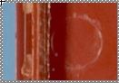
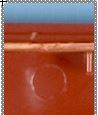
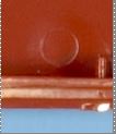
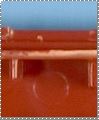
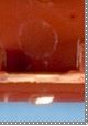


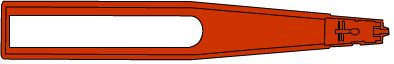
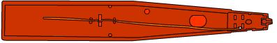
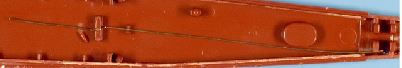
In this piece we can see evidence of the fabrication
process - injection moulding. See if you can spot the marks made by
the mould and click 'Show' below to see them up close. This piece is
made of the same material as the top - ABS, click 'Continue' to return
to the main screen and click on the top of the case for more information.
Click on the components to dismantle the article