Location of the Neutral Axis for a Bi-layer System
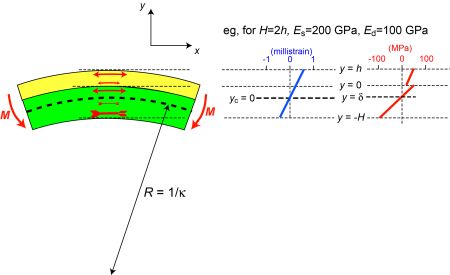
The figure below shows how the application of a bending moment, M, creates curvature, which is equal to the through-thickness strain gradient. Its magnitude depends on the applied moment and the beam stiffness of the sample. An example strain gradient is shown in the figure. Using the stiffness values shown, corresponding stresses can be found and these are also plotted.
The force balance
\[ b\mathop \smallint \limits_{ - H}^h \sigma (y) dy = 0 \]
can be divided into contributions from the two constituents and expressed in terms of the strain
\[ b\mathop \smallint \limits_{ 0}^h {E_d}\epsilon (y) dy + b\mathop \smallint \limits_{ - H}^0 {E_s}\epsilon (y) dy = 0 \]
which can then be written in terms of the curvature (through-thickness strain gradient) and the distance from the neutral axis
\[ b\mathop \smallint \limits_{ 0}^h {E_d} \kappa\ (y - \delta) dy + b\mathop \smallint \limits_{ - H}^0 {E_s}\kappa\ (y - \delta) dy = 0 \]
Removing the width, b, and curvature, Κ, which are constant, this gives
\[ {E_s}\left[ \frac{{y^2}} {2} - \delta y \right]^h _{0} + {E_d}\left[ \frac{{y^2}} {2} - \delta y \right]^0 _{-H}= 0 \]
\[ {E_d}\left( \frac{{h^2}} {2} - \delta h \right) + {E_s}\left( \frac{{-H^2}} {2} - \delta H \right)= 0 \]
This can be rearranged to give an expression for the location of the neutral axis
\[ \delta \left( {{E_d}h + {E_s}H} \right) = \frac{{1}}{2} {\left( {{E_d}{h^2} - {E_s}{H^2}} \right)} \]
\[ \delta = \frac{{\left( {{h^2}{E_d} - {H^2}{E_s}} \right)}}{{2\left( {h{E_d} + H{E_s}} \right)}} \]