Proton exchange membrane fuel cells (PEMFCs)
Low temperature cells
The proton exchange membrane (a.k.a. polymer electrolyte membrane) fuel cell uses a polymeric electrolyte. This proton-conducting polymer forms the heart of each cell and electrodes (usually made of porous carbon with catalytic platinum incorporated into them) are bonded to either side of it to form a one-piece membrane-electrode assembly (MEA). A quick overview of some key advantages that make PEMs such a promising technology for the automotive markets:
- Low temperature operation, and hence
- Quick start up
- No corrosive liquids involved
- Will work in any orientation (or zero g for that matter)
- Thin Membrane-electrode assemblies allow compact cells
![]()
Brief history
The PEM fuel cell was developed in the 1960’s in General Electric’s labs. As with so many technologies, the space program and military funded research fast-forwarded it’s development. PEM membranes were first applied to a US Navy project and projects for the US Signal Corps. PEM cells were used in NASA’s Gemini program, which was to serve as a means of testing technology for the Apollo missions. Batteries were not suitable for a journey to the moon because of the extended flight duration. Early PEM systems were, however, unreliable and plagued with leakages and contamination. The systems installed in Gemini spaceships had an operational lifetime of just 500 hrs, although this was considered suitable. Another issue was the water management systems, which are required to keep the membrane hydrated to the correct extent. Apollo designers opted for the more mature technology of AFCs, as did the Space Shuttle designers in the 70's. Recently however, as part of NASA’s program of continuous upgrade on the Shuttles, PEM systems have replaced the aging AFC technology as the primary power source for the Shuttles’ systems. GE decided to abandon their research on PEMFCs in the 70’s, probably due to the cost. At that time, the catalysis required 28 mg of Platinum per cm2 of electrode, compared to the current figure of 0.2 mg cm–2, or less.
Automobiles are arguably one of the most important consumer products on the planet. The finite fuel reserves, which they are chewing through, are not currently a limiting factor, but they will be soon. Much investment has been aimed at developing fuel cell technology for the automotive industry and the electrolyte of choice is the PEM. We’ll look at the problems which automotive companies need to overcome before fuel cell cars hit the street.
However, recent developments in PEMFCs have brought their current densities up to around 1 A cm–2 and cut the platinum requirement to 1% of what used to be needed. The scope of PEMFCs is, arguably, wider than that of any other power supply technology; with the potential to power a range of devices from mobile phones and laptops to busses, boats and houses.
![]()
Construction of the PEM cell
The PEMFC is constructed in layers of bipolar plates, electrodes and membranes:
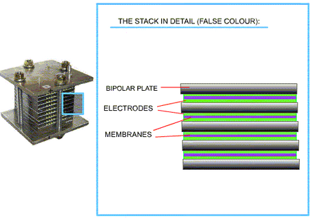
PEMFC components
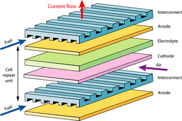
Each individual cell produces about 0.7 V EMF when operating in air, as calculated by the expressions outlined in the efficiency section. In order to produce a useful voltage, the electrodes of many cells must be linked in series. In addition to connecting the cells, we must ensure that reactant gases can still reach the electrodes and that the resistance of the electrodes has a minimal effect. If, for example, we were to simply wire up the edge of the anode of one cell to the cathode of another, electrons would have to flow across the face of the electrodes. Each cell only produces ~0.7 V, even a small reduction in this isn’t permissible, so cells aren’t normally wired up this way.
A Bipolar Plate is used to interconnect the anode of one cell to the cathode of the next. It must evenly distribute reactant gases over the surface of the anode, and oxygen/air over the cathode. Bipolar plates may also need to carry a cooling fluid, and in addition, need to keep all these gases and cooling fluids separate. Design considerations:
- The electrical contacts should be as large as possible
- The plate should be thin to minimise resistance
- Gas needs to flow easily across the plate
Often these factors are antagonistic to each other, for instance, large contact area would reduce the width of the gas channels. A very simple bipolar plate might look like this:
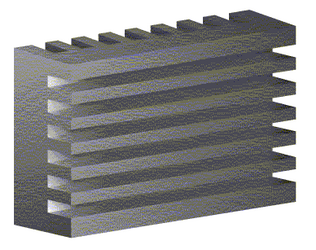
A typical bipolar plate (Left) found in a plate-type PEM assembly (Right)
Reactant gases flow at right angles to each other. In a simple plate design as above, the channels extend right to the edge. The reactant gases would probably be supplied to the system via external manifolding in this case.
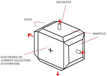
External manifolding
External manifolding is a very simple solution, and therefore carries out the job cheaply, but the technique has two major disadvantages. 1) The gaskets needed to seal the plates don’t form a tight seal where the channels come to the edge of the plate, leading to localised leaks of the reactant gases. 2) Additional channels for cooling fluids are very difficult to incorporate into an externally manifolded system, so all the cooling must be done by the air flowing across the cathode. This means more air than is necessary for the reaction must be pumped through the channels, which in turn means the channels must be wider, that the chance of leaks is increased and that some of the energy produced must be used to power blowers. Whilst simplicity is always a bonus, external manifolding is rarely used in modern systems.
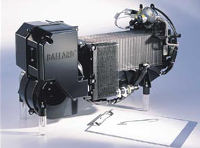
In this image of a Ballard Nexus™ fuel cell system, the fan used to blow air through the stack for cooling is visible on the left of the stack.
DoITPoMS standard terms of use
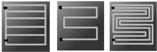
Most modern bipolar plates make use of internal manifolding. The three examples below show how this might be achieved. In each case, the channels do not run to the edge of the plates so a gasket could be fitted here and a gas-tight seal would be more easily achieved.
Internal manifolding
- The design on the left is a fairly simple parallel channels design; reactant gases would be blown into one end of the channel through one hole, and removed at the other hole. There are many different designs possible, and designers of bipolar plates are yet to reach an agreement on which type is best. In parallel designs, water or gas may build up along one of the channels causing a temporary blockage. In this case the reactants will happily continue to pass through the other channels and not clear the blockage.
- The second design, a serpentine design, guarantees that if reactants are flowing at all, they’re flowing all along the channel and blockages are easily cleared. The problem in this case is that it takes more effort to push reactants through the long, winding path.
- The third design is more of a compromise between the two and is the type of thing often seen in bipolar plate design. The channels are typically about 1 mm in width and depth. The pressure difference between the start and end of a channel must be engineered to overcome the surface tension of water droplets forming on the channel walls in order to clear blockages. Ballard, for example, achieve this pressure difference with rectangular plates in which the gases run across the long axis in a long parallel design.
The material properties of a bipolar plate, as summed up by Ruge and Büchi (2001), must take into account several important factors:
- Electrical conductivity >10 S cm–1
- Heat conductivity of 20 W m–1 K–1 if cooling fluid is integrated, 100 W m–1 K–1 if heat is removed from the edges.
- Gas permeability < 10–7 mbar L s–1 cm–2
- Resistant to corrosion in an environment of acidic electrolyte, hydrogen, oxygen, heat and humidity.
- Reasonably high stiffness E > 25 MPa
- As ever, it should cost as little as possible.
The plates must also be manufactured so that they are:
- Thin for maximum stack volume
- Light for minimum stack mass
- Able to be produced quickly with a short cycle time
These various and difficult specifications which must be met, along with the fact that modern electrodes require very little catalytic platinum, mean that the bipolar plate is the most expensive part of a modern fuel cell.
![]()
![]() Materials for constructing bipolar plates
Materials for constructing bipolar plates
![]()
PEMFCs without bipolar plates
As discussed, bipolar plates may provide excellent contact between cells, but they are expensive and complex. Some manufacturers, often on the smaller industrial scale, choose different techniques to link their cells. Cells could be connected simply edge to edge, reducing the possibility of leakage. One manufacturer (Intelligent Energy) produces cells with stainless steel bases through which hydrogen channels pass. The cathode current collector is a porous metal and these individual cell units are simply stacked with a piece of corrugated stainless steel between them. It’s a simple solution which may gain popularity.
In conclusion, we should note that although a broad range of bipolar plates techniques exist, none of them fully meet the criteria set above. There is lots of development still to be done in this area before we meet a new industry standard.