Hencky relations
The equilibrium equations for plane strain are:
$$\frac{{\partial {\sigma _{xx}}}}{{\partial x}} + \frac{{\partial {\tau _{xy}}}}{{\partial y}} = 0$$
$$\frac{{\partial {\tau _{xy}}}}{{\partial x}} + \frac{{\partial {\sigma _{yy}}}}{{\partial y}} = 0$$
Unless τxy = ± k, where k is the shear yield stress, the x- and y-directions (or axes) will not correspond to the directions of the α- and β-slip lines, which are themselves at ± 45° to the directions of principal stresses acting on the element.
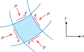
In general, we need to examine the stresses on a small curvilinear element in the x-y plane upon which a shear stress and a hydrostatic stress are acting, and where the principal stresses are – p – k and – p + k for a situation where there is plane strain compression, such as in forging or indentation in which k is a constant but p can vary from point to point:
We can then identify on this diagram the directions of principal stress σ1 and σ2 (remembering that σ1 > σ2), and which of the lines are α-lines and which are β-lines. We can also specify the angle φ of the α-lines with respect to the x-axis:
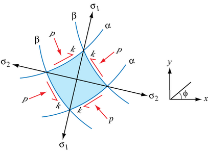
Suppose that the α-slip line passing through the element makes an angle φ with respect to reference x- and y-axes, as in the above diagram. The β-slip line must then make an angle of 90° + φ with respect to the x-axis, so that an anticlockwise rotation from the α-slip line to the β-slip line crosses the direction of maximum principal stress, σ1.
The direction parallel to the principal stress σ1 makes an angle of 45° + φ with respect to the x-axis and the direction parallel to the principal stress σ2 makes an angle of 135° + φ º 45° – φ with respect to the x-axis.
On a Mohr’s circle, this all looks like:
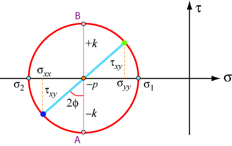
where A and B represent the stress states along the α- and β-lines respectively.
Hence, from the above,
$$\begin{array}{l} {\sigma _{xx}} = - p - k\sin 2\varphi \\ {\sigma _{yy}} = - p + k\sin 2\varphi \\ {\tau _{xy}} = k\cos 2\varphi \end{array}$$
while the tensile stress in the z-direction in plain strain plastic yielding is simply:
$$\frac{1}{2}\left( {{\sigma _{xx}} + {\sigma _{yy}}} \right) = - p$$
Substituting these expressions into the equilibrium equations
$$\frac{{\partial {\sigma _{xx}}}}{{\partial x}} + \frac{{\partial {\tau _{xy}}}}{{\partial y}} = 0$$
$$\frac{{\partial {\tau _{xy}}}}{{\partial x}} + \frac{{\partial {\sigma _{yy}}}}{{\partial y}} = 0$$
and recognising that k is a constant independent of x and y, we obtain two equations for p and φ as a function of x and y:
$$\begin{array}{l} - \frac{{\partial p}}{{\partial x}} - 2k\cos 2\varphi \frac{{\partial \varphi }}{{\partial x}} - 2k\sin 2\varphi \frac{{\partial \varphi }}{{\partial y}} = 0\\ - 2k\sin 2\varphi \frac{{\partial \varphi }}{{\partial x}} - \frac{{\partial p}}{{\partial y}} + 2k\cos 2\varphi \frac{{\partial \varphi }}{{\partial y}} = 0 \end{array}$$
For φ = 0°, in which case the α and β lines coincide with the external x- and y-axes respectively at a particular position, these equations become
$$(1)\;\;{\rm{ }}\frac{\partial }{{\partial x}}\left( {p + 2k\varphi } \right) = 0$$ $$(2)\;\;{\rm{ }}\frac{\partial }{{\partial y}}\left( {p - 2k\varphi } \right) = 0$$
Integrating these equations we find
$$\begin{array}{l} (1)\;\;{\rm{ }}p + 2k\varphi = {f_1}(y) + {C_1}\\ (2)\;\;{\rm{ }}p - 2k\varphi = {f_2}(x) + {C_2} \end{array}$$
as the most general form of the solutions of these two partial differential equations. However, we know that when φ is exactly zero, p must have the same value in both (1) and (2). Hence it follows that f1(x) = f2(y) = 0.
In general for points in a slip-line field we have therefore proved that the Hencky relations have to be satisfied:
The hydrostatic pressure p varies linearly with the angle φ turned by a slip line. p + 2kφ is constant along an α line where the angle φ is in radians. |