Mechanisms of Plasticity (all content)
Note: DoITPoMS Teaching and Learning Packages are intended to be used interactively at a computer! This print-friendly version of the TLP is provided for convenience, but does not display all the content of the TLP. For example, any video clips and answers to questions are missing. The formatting (page breaks, etc) of the printed version is unpredictable and highly dependent on your browser.
Contents
Aims
After this TLP. You should be able to:
- Understand how new dislocations are generated from a Frank-Read source
- Calculate the critical shear stress required to operate a Frank-Read source
- Describe the interactions between two dislocations
- Explain the origin of solute-solution strengthening in terms of the interactions between the strain fields of dislocations and solute atoms
- Describe the formation of Lomer lock
- Understand how jogs and kinks are formed, and their significance in work hardening
- Understand the significance of Frank-Read source, Lomer lock, jogs and kinks in forest hardening
- Describe stage 1 and 2 in the deformation of a single crystal
- Explain the process of grain boundary hardening in a poly-crystal
Before you start
This TLP assumes that you have some basic knowledge on dislocation theory. However, the following TLPs could be helpful:
Introduction to Dislocations (Basic information about dislocations)
Slip in Single Crystals (Information about slip in an fcc metal, including stage I and II of its deformation)
Introduction
This TLP concerns the topic of crystal plasticity. Plasticity is defined as:
The deformation of a (solid) material undergoing non-reversible changes of shape in response to applied forces.

Figure 1: The true stress-strain curve of a crystal.
During plastic deformation, the total strain of a metal is the sum of the elastic and plastic strain. However, the elastic strain is typically less than 1%, which is much less than the plastic strain. This can be seen from the nearly vertical elastic region in the true stress-strain curve in Figure 1.
Crystals undergo work hardening when they are deformed plastically. Work hardening, also known as strain hardening, describes the increase of the stress level necessary to continue plastic deformation. It arises as mobile dislocations are impeded by jogs and Lomer locks as the crystals are deformed.
From Figure 1, it can be seen that the work hardening rate (the gradient of the true stress-strain curve) decreases progressively with increasing strain and eventually approaches a plateau. This is due to the competing effect between the generation of new dislocations (as more Frank-Read sources are operated), the resistance from jogs, locks and tangles, and the processes which allow them to be organised and to annihilate each other (climb and cross-slip).
This TLP explores the plasticity of crystals by first introducing some of the aspects of single crystals. These include the Frank-Read source, dislocation interactions, the formation of Lomer lock and jogs, and the process of climb and cross-slip. This will be followed by an example on the deformation of a single crystal, where the significance of these aspects in stage I and II is discussed. Finally, it will discuss the deformation of poly-crystals by focusing on grain boundary hardening.
Dislocation generation
The Frank-Read source
In order to explain the plastic behaviour of a single crystal, a mechanism by which dislocations are generated must be formulated. Such a mechanism is realised on the basis of the two experimental observations:
1. Surface displacement at a slip band is due to the movement of about 1000 dislocations over the slip plane. The number of dislocation sources initially present tin a metal could not account for the observed slip-band spacing and displacement unless there were some way in which each source could produce large amounts of slip before it became immobilized.
2. If there were no source generating dislocations, cold-work should decrease, rather than increase, the density of dislocations in a single crystal.
The mechanism by which dislocations are generated (multiplied) was proposed by Frank and Read in the 1950s and is known as the Frank-Read source.
Below is an animation which explains how dislocations are generated from a Frank-Read source.
Animation captions:
- When a tensile stress is applied to a single crystal, the shear stress exerts a force \( F = \tau{ *b} \) on the dislocation line, which is pinned at both ends. This could occur if the two ends were nodes where the dislocation in the plane of the paper intersects dislocations in the other slip planes, or the pinning could be caused by existing precipitates
- The shear stress causes the dislocation line to bow outwards, balancing the line tension and the force due to the applied shear stress.
- The shear stress reaches a maximum when the segment becomes a semicircle.
- The dislocation segment continues to expand until the ends annihilate each other (as they have opposite burgers vectors), forming a dislocation loop.
- The loop continues to expand, and a new dislocation line is formed. The process can repeat itself sending out many loops.
Here is a TEM video showing a real Frank-Read source in action:
The minimum stress required to operate a Frank-Read source

Figure 2: Force diagram of a Frank-Read source. The dislocation segment is pinned at both ends by forest dislocations.
The force on the dislocation line, which has a distance d between the pinned ends, when a shear stress τ is applied is \( F = \tau{ bd} \). This force is balanced by the line tension (energy/length) of the dislocation, which is ≈ Gb2.
At the pinning ends, the vertical component of the force is 2Gb2sin(θ). This force reaches a maximum 2Gb2 when the dislocation is bowed into a semicircle (θ) = 90). Hence, the minimum stress required to operate the Frank-Read source is when τbd = 2Gb2, i.e. \[ \tau = 2\frac{{Gb}}{d} \]
Since the distance d between the pinned ends is related to the dislocation density ρ by \( \rho = 1/{d^2} \), the minimum stress can be written:
\[ \tau = 2Gb\sqrt \rho \]
The simulation below allows you to explore the effect of changing each parameter in the above equation on the minimum stress. Note that d is changed by changing the (forest) dislocation density (here we model the forest dislocations as pinning sites).
Dislocation interactions
Dislocation-dislocation interactions
Around a dislocation, the atoms are displaced from their normal positions. The atomic displacements are equivalent to that caused by elastic strains arising from external stresses. For example, the extra half plane of the edge dislocation puts the region above the slip plane into hydrostatic compression, whilst the region below the slip plane goes into tension.
When dislocations move under a tensile stress, their stress fields interact. As the elastic strain energy is proportional to the square of the local strain, it is energetically favourable for the stress fields to configure themselves to minimise this strain. The resultant configuration depends on the sign of the two dislocations interacting with each other. Dislocations of the same sign have the same burgers vector. Conversely, dislocations of opposite sign have opposite burgers vectors. (For more information about Burgers vector, see Introduction to Dislocations).
Below is an animation showing the attraction and repulsion of dislocations on the same and different slip plane
Dislocation-solute atoms interactions
Dislocations also interact with the solute atoms in a crystal. The solute atoms can be either interstitial or substitutional. The stress field created by the solute atom is spherically symmetric. The stress field is compressive if the solute atom is larger than the lattice atoms. On the other hand, the stress field is tensile if the solute atom is smaller than the lattice atoms.
The spherical symmetry of the stress fields induced by the substitutional solute atoms means the fields contain no shear stress component. Hence, they do not interact with screw dislocations, which are pure shear dislocations (i.e. screw dislocations have no hydrostatic tension or compression). However, the stress fields created by substitutional solute atoms will interact with the stress fields of edge dislocations. This will lead to favourable relative arrangements of dislocations and solute atoms, such that the strain energy is minimised.
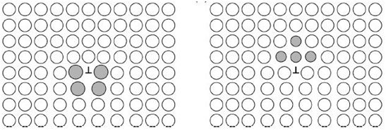
Figure 3: (Left) Larger solute atoms in the tensile field of an edge dislocation and (Right) smaller solute atoms in the compressive field of an edge dislocation. (Source of image: N. Jones, Course E: Mechanical Behaviours of Materials, Part 1A (2016), p. 60)
The interaction between dislocations and solute atoms leads to solute solution strengthening. If an edge dislocation interacts with a solute atom which is larger than the lattice atoms, the solute atom will reside below the extra half plane of atoms to relieve the hydrostatic tension (Figure 3). This causes the two stress fields to repel each other. On the other hand, if an edge dislocation interacts with a solute atom which is smaller than the lattice atoms, the solute atom will sit at the end of the extra half plane to relieve the hydrostatic compression. In both cases, an energetically favourable arrangement of the dislocation and the solute atom is formed, which tends to persist as it minimises the energy of the system. This effect retards dislocation motion and a greater shear stress is required to move the dislocation from this configuration than was necessary to move through the host lattice, which gives rise to solute solution strengthening.
Sessile dislocations
Lomer lock in fcc
A Lomer lock is a type of sessile dislocation which acts as a pinning point in forest hardening. Below is a an animation which explains the formation of Lomer lock.
Climb and cross slip
Climb and cross-slip are the two dominant processes by which dislocations become organised and annihilate each other by dislocation interactions.
Climb
Since the line and Burgers vector of an edge dislocation are perpendicular to each other, there is one plane in which the dislocation can slip. However, there is an alternative mechanism by which the dislocation can move to a different slip plane, known as climb. Climb is the mechanism of moving an edge dislocation from one slip plane to another through the incorporation of vacancies or atoms.
Climb can be either positive or negative. In positive climb, the dislocation acts as a vacancy sink, absorbing a vacancy to shift itself upwards relative to its initial position. In negative climb, the dislocation acts as a vacancy source. The vacancy at the bottom of the extra half plane is replaced by an atom, which causes the dislocation to shift downwards.
The following animation shows how positive dislocation climb occurs by the diffusion of vacancies around a crystal.
Cross-slip
Cross-slip is the movement of a screw dislocation from one allowable slip plane to another. Below is a video which explains how cross-slip work.
It should be noted that only perfect screw dislocations can cross-slip, as their line and Burgers vector are parallel to each other. Dislocations which have edge components can never cross slip.
Partial dislocations in an fcc system
Cross-slip becomes more complicated for an fcc metal. In an fcc metal, a perfect dislocation tends to dissociate into two partial dislocations and, therefore, cannot cross-slip when it dissociates. To understand this, consider the atomic packing on a closed-packed (111) plane in Figure 4:

Figure 4: Slip in a closed-packed (111) plane in an fcc lattice. (Source of image: G.E. Dieter, Mechanical Metallurgy (1988), p. 155)
The {111} planes are stacked on a sequence ABCABC…, and the Burgers vector \( {b_1} = \frac{a}{2}\left[ {10\overline 1 } \right] \) defines one of the slip directions. However, the same shear displacement can be accomplished by the two-step path b2 + b3. According to Frank’s rule, the latter is more energetically favorable. Hence, the perfect dislocation is decomposed into two partials:
\[ \frac{a}{2}\left[ {10\overline 1 } \right] \to \frac{a}{6}\left[ {2\overline 1 \overline 1 } \right] + \frac{a}{6}\left[ {11\overline 2 } \right] \]Slip by this two-step process creates a stacking fault ABCAC\( \vdots \)ABC in the stacking sequence. The two partial dislocations, which are separated by the stacking fault, are collectively referred to as an extended dislocation. Since the extended dislocation has both edge and screw components, it defines a specific slip plane, in this case the {111} plane of the fault. Consequently, the two partial dislocations are constrained to move in this plane and cannot cross slip unless the partials recombine to form a perfect dislocation again (This recombination of two partials is referred to as constriction).
It should be noted that while a pair of dissociated partials does need to be forced back together into a single perfect (screw) dislocation in order to be able to cross-slip, this need not happen along the complete length of the dislocation at the same time. What usually happens is that a local constriction (to a short length of perfect (screw) dislocation) is formed, this small section cross-slips onto the new glide plane, where it again separates into two partials (different partials from the original pair). Figure 5 shows an example where it is energetically easier for constriction to take place along a certain length than the complete length becoming a perfect dislocation, and cross-slipping, at the same time.

Figure 5: Sequence of events envisaged during the cross-slip process. Four stages in the cross slip of a dissociation (a) by the formation of a constricted screw segment (b). The screw has dissociated in the cross-slip plane at (c) (Source of image: Hull and Bacon, 2011).
Below is an animation showing how cross-slip happens in an fcc crystal.
The influence of stacking-fault energy on the availability of cross-slip
It is important to note that cross-slip is more difficult in metals with a low stacking-fault energy (i.e. a wide stacking fault). This is because the partial dislocations, which are well-separated, cannot recombine to form a perfect dislocation to cross slip. For example, cross-slip is not observed in copper (which has a stacking-fault energy of 45 mJm-2, but is quite prevalent in aluminium (which has a stacking-fault energy of 166 mJm-2).
Stacking-fault energy is also particularly important at relatively low temperatures, since climb is then very difficult and cross-slip is virtually the only mechanism by which dislocations can do anything other than glide on a single slip plane (which is quite a severe limitation in terms of a region trying to undergo a general shape change, which requires independent slip systems)
Dislocation intersections to form jogs and kinks
Introduction
Commonly, dislocations are generated and move on more than one slip system simultaneously. These dislocations must therefore intersect each other, leading to the formation of jogs. Jogs refer to, confusingly, both a jog and a kink. A jog is a short section with length and direction equal to b of the other dislocation and lies out of the slip plane. A kink is a short break in the dislocation line which lies in the slip plane. The formation of jogs has two important consequences:
-
Jogs increase the lengths of the dislocation lines. Hence the intersection of dislocations involve the expenditure of additional energy.
-
Jogged dislocations will move less readily through the crystal, so they play an important role in work hardening.
Formation of a jog
Below is a video showing how a jog is formed when two edge dislocations intersect.
Formation of a kink
Kinks are formed when the jogs resulted froma dislocation intersection lie in the slip plane instead of normal to it. This can occur when two orthogonal edge dislocations with parallel Burgers vectors intersect each other. As kinks lie in the same plane, they do not inhibit movement of dislocation (i.e. they are glissile). Kinks may also assist dislocation motion, as atoms or vacancies diffusing to them can enable the dislocation to move at stresses below the critical resolved shear stress. In addition, they are often unstable since during glide they can line up and annihilate the offset.

Figure 6: Intersection of two edge dislocations with parallel Burgers vectors. (Left) Before intersection; (Right) after intersection. (Source of image: G.E. Dieter, Mechanical Metallurgy (1988), p. 171)
Contribution to work hardening

Figure 7: Intersection of two screw dislocations. (Left) Before intersection; (Right) after intersection. (Source of image: G.E. Dieter, Mechanical Metallurgy (1988), p. 172).
From the viewpoint of plastic deformation, the most important type of dislocation intersection is the intersection of two screw dislocations (Figure 7). The intersection of two screw dislocations produces jogs of edge orientation in both screw dislocations (line vectors of the jogs are perpendicular to the burgers vectors of the screw dislocations).

Figure 8: Movement of an edge-oriented jog on screw dislocation. The jog is constrained to move along the dislocation in plane AA’BB’. (Source of image: G.E. Dieter, Mechanical Metallurgy (1988), p. 172)
Since an edge dislocation can glide freely only in the plane containing its line and Burgers vector (Plane AA’BB’), the only way the jog can move by slip (conservative motion) is along the axis of the screw dislocation. If the screw dislocation is to slip to a new position, such as MNN’O, it can only do so by taking its jog with it by a non-conservative process such as climb.
Because dislocation climb is a thermally activated process, the movement of the jogged screw dislocation will be temperature-dependent. At temperatures where climb cannot occur, the motion of screw dislocations will be impeded by jogs (i.e. the jogs are sessile) and so the crystal becomes work hardened.
Deformation of a single crystal

Figure 9: The stress-strain curve of a single crystal. The gradient of the linear region in stage ll is G/200.
When a single crystal is plastically deformed, different behaviors are observed in its stress-strain curve depending on the strain. These behaviors are divided into three stages (Figure 9). Here, only stage l and ll will be discussed.
Stage 1
This is a stage of low linear hardening which may be absent, or account for as much as 40 percent shear strain depending on the testing conditions (mainly how much lattice rotation is required to start a second slip system deforming, see Slip in Single Crystals). Since only one slip system is operative, the dislocations can glide easily without being impeded by dislocations from other slip systems. Hence, this stage is often referred to as ‘easy glide’.
In stage l, dislocations of a single slip system which are parallel to each other all glide in one direction. Experimental data has shown that there is a small but finite work hardening rate associated with this stage. This is due to the accumulation of dislocation debris in the form of dipoles.
The extent of stage 1 depends on the purity of the crystal. If the impurities form a dispersion of second phases (e.g. silicon and iron phases in aluminium), stage 1 hardening is reduced or even eliminated. This is because the small inclusions encourage localized slip on other than the primary slip plane, so other slip systems are activated. On the other hand, impurities which form a solid solution with the crystal tend to enhance the extent of stage 1.
Stage ll
As the crystal is deformed, the tensile axis rotates towards the slip direction. Stage 2 is initiated when the tensile axis has rotated to a position where two slip systems share the largest Schmid factor. At this stage, two slip systems are activated, forming a secondary slip system in addition to the primary system which exists in stage 1. The dislocations that move on both slip systems can interact with each other to form jogs, locks and pile ups. Consequently, the crystal becomes work-hardened in this stage.
Stage 2 work hardening is characterized by an approximately linear stress-strain curve whose slope (the hardening rate) is about G/200 (where G is the shear modulus), which has a mild dependence on temperature or strain rate (i.e. the hardening rate is constant).
Using dimensional analysis, it can be shown that the fundamental relationship for the flow stress \( \tau \) in stage 2 is:
\[ \tau = \alpha \;b\;\;G\sqrt \rho \]This is known as the Taylor equation. Here α is a dimensionless number, G is the shear modulus, b is the Burgers vector and ρ is the forest dislocation density of the system.
The term α represents an average interaction strength between dislocations and its value depends on the inherent complexity of detailed dislocation theory. The interaction can vary from entirely elastic between dislocations with perpendicular Burgers vectors, to energy storing when intersection leads to formation of a jog. The magnitude is typically in the range 0.5 – 1.0.
Forest hardening

Figure 10: An active dislocation gliding in the primary slip plane. The pinning points are created by the intersections between the active and the forest dislocations.
It has been mentioned that two slip systems are activated during stage ll of the deformation of a single crystal. However, the plastic flow of the crystal is mainly governed by the primary slip system (i.e. it is an active slip system), where the primary dislocations can move freely. The dislocations in the other slip system, however, are immobile and are termed the forest dislocations.
Forest hardening is the dominant mechanism in stage ll of the single crystal deformation. The active dislocations gliding in the primary slip plane get stuck at obstacles when they intersect with the forest dislocations. These obstacles, or pinning points, are either jogs (when dislocations intersect each other) or Lomer locks (when dislocations react together). During stage ll, the number of fixed obstacles will increase as more Frank-Read sources are operated, which leads to an increase in the number of forest dislocations.
Deriving an expression for the constant hardening rate
It has been mentioned that the hardening rate of stage ll is constant, with a typical value of G/200. We now aim to derive an expression for this hardening rate by considering the movement of an active dislocation in the primary slip system. Consider a segment of dislocation of length l pinned at both ends. The mean free path of the dislocation segment is λ. The change in the dislocation density with respect to the strain is:
\[ \frac{{{\rm{d}}\rho }}{{{\rm{d}}\gamma }} = \frac{{{\rm{d}}l}}{{b{\rm{d}}a}} \]where dl is the change in the line length of the dislocation segment and da is the area swept by the dislocation as it moves.
From Figure 10, we have dl = l and da = λl, hence:
\[ \frac{{{\rm{d}}\rho }}{{{\rm{d}}\gamma }} = \frac{1}{{b\lambda }} \]Differentiate the Taylor equation:
\[ \frac{{{\rm{d}}\tau }}{{{\rm{d}}\gamma }} = \frac{1}{2}\;\alpha \;b\;G\;{\rho ^{ - \frac{1}{2}}}\;\frac{{{\rm{d}}\rho }}{{{\rm{d}}\gamma }} \] \[ \frac{{{\rm{d}}\tau }}{{{\rm{d}}\gamma }} = \frac{1}{2}\;\alpha \;b\;G\;{\rho ^{ - \frac{1}{2}}}\;\frac{1}{{b\lambda }} \] \[ \frac{{{\rm{d}}\tau }}{{{\rm{d}}\gamma }} = \frac{{\alpha \;\;G}}{{2\;\lambda \;\sqrt \rho }} \]The mean free path λ is usually a small multiple, of order 10, of the mean dislocation spacing \( \frac{1}{{\sqrt \rho }} \) and so it follows that the expression above gives a reasonable value for the hardening rate of about G/200.
Dislocation dynamics
Dislocation dynamics aims to simulate the dynamic, collective behavior of individual dislocations and their interactions. The following video uses dislocation dynamics to simulate the behavior of dislocations when an fcc single crystal is deformed. Although it is a single crystal, it does not exhibit any easy glide and multiple slips are initiated at the start.
Continuum models describing the true stress-strain curves
The continuum models which describe the true stress-strain curves, such as Ludwik-Hollomon and the Voce equation, are covered in the mechanical testing of metals TLP.
Grain boundary hardening of poly-crystals
Compared to single crystals, poly-crystals tend to have higher yield stresses. This is because each grain in the poly-crystals has to undergo a complex shape change which is consistent with those of their neighbors, requiring multiple slips from the start. Therefore, unlike single-crystals, poly-crystals do not exhibit any kind of ‘easy glide’ when they are deformed.
Below is an explanation of how grain boundary hardening arises in a poly-crystal:
Summary
This TLP has covered the following points:
1.New dislocations are generated from a Frank-Read source. The minimum shear stress required to operate a Frank-Read source, which is found by balancing the force on the dislocation and the line tension, is: \[ \tau = 2\frac{{Gb}}{d} \] Frank-Read source is important as it is the mechanism by which dislocation density increases as a material is work-hardened.
2.A dislocation can interact with either another dislocation or a solute atom. When dislocations interact with each other, they can either repel (if they have the same sign) or annihilate (if they have opposite signs). On the other hand, when a dislocation interacts with a solute atom, an energetically favorable arrangement is formed, leading to solute-solution strengthening.
3.A Lomer lock is a type of sessile dislocation formed when the plane which contains the line and Burgers of the edge dislocation is not a close-packed slip plane of the system.
4.Climb and cross-slip are the two processes by which dislocations can become organised and annihilate. Climb is the mechanism of moving an edge dislocation from one slip plane to another through the incorporation of vacancies or atoms. Cross-slip is the movement of a screw dislocation from one allowable slip plane to another. Cross-slip is favoured in metals with a high stacking-fault energy.
5.Jogs are formed by dislocation intersections. In particular, the intersection between two screw dislocations is crucial to work hardening.
6.The two stages of the plastic deformation of a single crystal are discussed. It is important to note that stage l only exists in single crystals, as only one slip system is operated (Poly-crystals do not exhibit stage l as multiple slips are initiated from the start). Stage ll, where the hardening rate is constant, is governed by forest hardening. The flow stress at this stage is given by the Taylor equation: \[ \tau = \alpha \;b\;\;G\sqrt \rho \]
7.Forest hardening arises when the active dislocations in the primary slip system are impeded by the forest dislocations in the secondary slip system. The pinning points, which are created by the intersections between the active and forest dislocations, are either jogs or Lomer locks.
8.The typical value of the hardening rate is \( G \)/200. The expression for the hardening rate is found by considering the movement of a dislocation segment:
\[ \frac{{{\rm{d}}\tau }}{{{\rm{d}}\gamma }} = \frac{{\alpha \;\;G}}{{2\;\lambda \;\sqrt \rho }} \]
9.Poly-crystals have higher yield stresses than single-crystals as each grain needs to undergo a shape change which is consistent with those of their neighbor, requiring multiple slips from the start. In addition, the yield stress of a poly-crystal is related to the grain size by the Hall-Petch relationship: \[ {\sigma _y} = {\sigma _0} + \frac{k}{{\sqrt D }} \]
Questions
Quick questions
You should be able to answer these questions without too much difficulty after studying this TLP. If not, then you should go through it again!
-
What is the ratio of the minimum shear stress required to operate a Frank-Read source for work-hardened copper (ρ = 1014 m-2) and annealed copper (ρ = 1010 m-2)?
-
Which of the following about cross-slip is true?
-
Which type of intersection is most important to work hardening?
-
Which of the following is not a pinning site in forest hardening?
-
Which of the following about poly-crystals is/are true?
Deeper questions
The following questions require some thought and reaching the answer may require you to think beyond the contents of this TLP.
-
Explain why the intersection of two screw dislocations is important to work hardening.
Going further
Books
The following books contain extensive information about Frank-Read source, jogs formation, Lomer locks and single-crystals deformation.
R.W.K. Honeycombe, The Plastic Deformation of Metals, Second Edition, 1984, ISBN: 0-7131-3468-2
W.F. Hosford, Mechanical Behavior of Materials, Second Edition, 2010, ISBN: 978-0-521-19569-0
G.E. Dieter, Mechanical Metallurgy, SI Metric Edition, 1988, ISBN: 0-07-100406-8
For a more detailed and mathematical description of forest hardening and single-crystals deformation, consult:
A.S.Argon, Strengthening mechanisms in crystal plasticity, 2008, ISBN: 978-0-19-851600-2
Other resources
A.D. Rollett, U.F. Kocks, A Review of the Stages of Work Hardening, 35-36 (1993) pp 1-18, 10.4028/www.scientific.net/SSP.35-36.1
U.F.Kocks, A Statistical Theory of Flow Stress and Work-hardening (1965)
Both contain a detailed discussion of forest hardening and single-crystals deformation.
Academic consultant: Rob Thompson (University of Cambridge)
Content development: Quincy Lin
Photography and video:
Web development: Lianne Sallows and David Brook
This DoITPoMS TLP was funded by the UK Centre for Materials Education and the Department of Materials Science and Metallurgy, University of Cambridge.