Atomic Scale Structure of Materials (all content)
Note: DoITPoMS Teaching and Learning Packages are intended to be used interactively at a computer! This print-friendly version of the TLP is provided for convenience, but does not display all the content of the TLP. For example, any video clips and answers to questions are missing. The formatting (page breaks, etc) of the printed version is unpredictable and highly dependent on your browser.
Contents
Main pages
Additional pages
Aims
On completion of this TLP you should:
- know the differences between single crystal, polycrystalline and amorphous solids
- be able to identify the characteristic features of single crystals and polycrystals
- understand the nature of crystal defects
- appreciate the use of polarised light to examine optical properties
Introduction
The fundamental difference between single crystal, polycrystalline and amorphous solids is the length scale over which the atoms are related to one another by translational symmetry ('periodicity' or 'long-range order'). Single crystals have infinite periodicity, polycrystals have local periodicity, and amorphous solids (and liquids) have no long-range order.
- An ideal single crystal has an atomic structure that repeats periodically across its whole volume. Even at infinite length scales, each atom is related to every other equivalent atom in the structure by translational symmetry.
- A polycrystalline solid or polycrystal is comprised of many individual grains or crystallites. Each grain can be thought of as a single crystal, within which the atomic structure has long-range order. In an isotropic polycrystalline solid, there is no relationship between neighbouring grains. Therefore, on a large enough length scale, there is no periodicity across a polycrystalline sample.
- Amorphous materials, like window glass, have no long-range order at all, so they have no translational symmetry. The structure of an amorphous solid (and indeed a liquid) is not truly random - the distances between atoms in the structure are well defined and similar to those in the crystal. This is why liquids and crystals have similar densities - both have short-range order that fixes the distances between atoms, but only crystals have long-range order.
The range of crystalline order distinguishes single crystals, polycrystals and amorphous solids. The figure shows how the periodicity of the atomic structure of each type of material compares.
Many characteristic properties of materials, such as mechanical, optical, magnetic and electronic behaviour, can be attributed to the difference in structure between these three classes of solid.
Single crystals: Shape and anisotropy
A single crystal often has distinctive plane faces and some symmetry. The actual shape of the crystal will be determined by the availability of crystallising material, and by interference with other crystals, but the angles between the faces will be characteristic of the material and will define an ideal shape. Single crystals showing these characteristic shapes can be grown from salt solutions such as alum and copper sulphate.
Gemstones are often single crystals. They tend to be cut artificially to obtain aesthetically pleasing refractive and reflective properties. This generally requires cutting along crystallographic planes. This is known as cleaving the crystal. A familiar example is diamond, from which decorative stones can be cleaved in different ways to produce a wide range of effects.
To see a variety of symmetrical naturally formed minerals, visit the mineral galleries website.
Consider the following three-dimensional shapes:
 |
Cube: 6 identical squares |
 |
Tetrahedron: 4 identical equilateral triangles |
 |
Octahedron: 8 identical equilateral triangles |
 |
Rhombohedron: 6 identical parallelograms with sides of equal length |
You can make your own cube, octahedron and tetrahedron by printing the following pages and following the instructions on them.
These three shapes are the most important in materials science, and you should be very familiar with them!
The symmetry exhibited by real single crystals is determined by the crystal structure of the material. Many have shapes composed of less regular polyhedra, such as prisms and pyramids.
 |
Hexagonal prism: 2 hexagons and 6 rectangles |
 |
Square-based pyramid: 4 triangles and a square |
Not all single crystal specimens exhibit distinctive polyhedral shapes. Metals, for example, often have crystals of no particular shape at all.
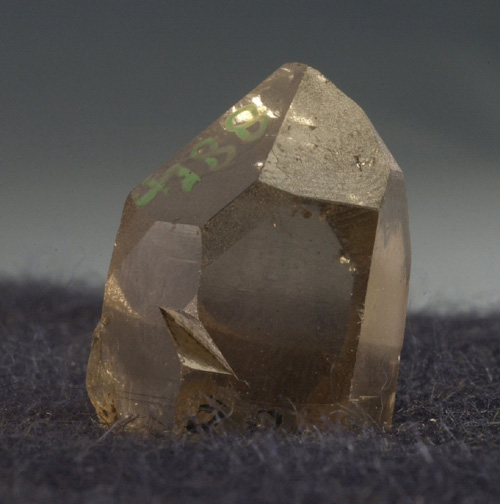 |
 |
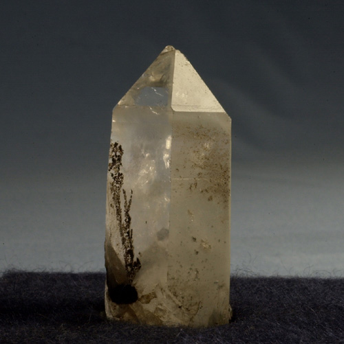 |
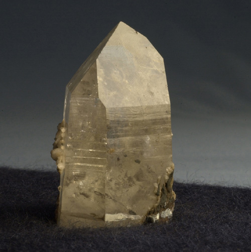
These quartz specimens show a range of shapes typically exhibited by crystals. (Click on an image to see a larger version.)
Most single crystals show anisotropy in certain properties, such as optical and mechanical properties. An amorphous substance, such as window glass, tends to be isotropic. This difference may make it possible to distinguish between a glass and a crystal. The characteristic shape of some single crystals is a clue that the properties of the material might be directionally dependent. The properties of polycrystalline samples can be completely isotropic or strongly anisotropic depending on the nature of the material and the way in which it was formed.
Single crystals: Mechanical properties
Gypsum can be cleaved along particular crystallographic planes using a razor blade. The bonding perpendicular to these cleavage planes is weaker than that in other directions, and hence the crystal breaks preferentially along these planes. Quartz and diamond do not have such distinct cleavage planes, and so cleaving these crystals requires much more effort and care.
There are distinct planes in the gypsum structure, with no bonding between them. These are the cleavage planes. It is much more difficult to cleave gypsum along planes other than these. In contrast, all of the planes in the quartz structure are interconnected and the material is much more difficult to cleave in any direction. This is a demonstration of a way in which the crystal structure of a material can influence its mechanical properties.

Certain crystals, such as gypsum, can be cleaved with a razor blade along particular crystallographically-determined planes. (Click on image to view larger version.)
Glass is impossible to cleave. As an amorphous substance, glass has no crystallographic planes and therefore can have no easy-cleavage directions. Glassy materials are often found to be mechanically harder than their crystalline equivalents. This is an example of how mechanical properties of crystals and amorphous substances differ.
Single crystals: Optical properties
Quartz crystals are birefringent, so they exhibit optical anisotropy. Consider plane polarised light passing through a birefringent crystal. Inside the crystal, the light is split into two rays travelling along permitted vibration directions (p.v.d.s). The two rays are subject to different refractive indices, so the light travelling along each p.v.d. reaches the opposite side of the crystal at a different time. When the two rays recombine, there is a phase difference between the two rays that causes the polarisation state of the transmitted light to be different from that of the incident light.
Optical anisotropy in thin samples can be observed by placing the sample between crossed polarising filters in a light box. The bottom filter, between the light source and the sample, is called the polariser. The top filter, between the sample and the observer, is called the analyser. The polariser and analyser have polarising directions perpendicular to one another.
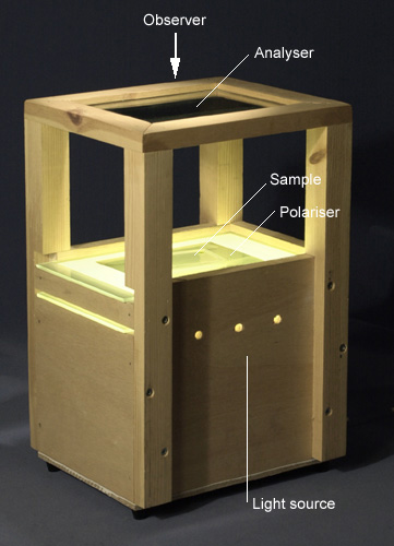
The apparatus used for examining optical anisotropy consists of a white-light source, two polarising filters and a frame to hold them apart so creating a working space.
When no sample is in place the light that reaches the analyser is polarised at 90° to the analyser's polarisation direction, so no light is transmitted to the observer. When a quartz sample (with favourable orientation, see later) is placed between the filters, the crystal changes the polarisation state of the light that is transmitted through it. When this light reaches the analyser, some component of it lies parallel to the polarisation direction of the analyser, and therefore some light is transmitted to the observer.
If a quartz slice shows optical anisotropy, the intensity of light transmitted through the analyser varies as a function of the angle of rotation of the quartz sample in the plane of the filters. At certain orientations, no light is transmitted. These 'extinction positions' are found at 90° intervals.
Video animation of anisotropic quartz rotated between crossed polarisers
When the same experiment is done using a piece of glass, it is found that light is not transmitted for any orientation. This is because the glass is optically isotropic, and does not change the polarisation state of the light passing though it.
In quartz, there is one direction of propagation for which no birefringence is observed. If a sample is cut so that the incident light is parallel to this direction, the sample behaves as if it is optically isotropic and no light is transmitted. The crystallographic direction that exhibits this property is known as the optic axis.
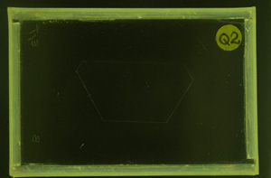
When the quartz sample is cut so that the incident light is parallel to the optic axis, no light is transmitted in any orientation.
This experiment demonstrates that some single crystals, such as quartz, show anisotropic optical properties. The phenomenon depends on the crystallographic orientation of the crystal with respect to the incident light. Amorphous materials like glass have no 'distinct' crystal directions, so anisotropic properties are generally not observed.
Polycrystals
Single crystals form only in special conditions. The normal solid form of an element or compound is polycrystalline. As the name suggests, a polycrystalline solid or polycrystal is made up of many crystals. The properties of a polycrystal are notably different from those of a single crystal. The individual component crystallites are often referred to as grains and the junctions between these grains are known as grain boundaries.
The size of a grain varies according to the conditions under which it formed. Galvanised steel has a zinc coating with visibly large grains. Other materials have much finer grains, and require the use of optical microscopy.
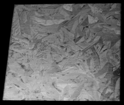
In galvanised steel, the grains are big enough to be seen unaided. The plate measures 5 cm across.
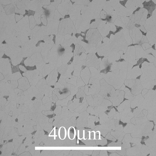
In many other metals, such as this hypoeutectoid iron-carbon alloy, the grains may only be seen under a microscope. (Click on image to see larger version.)
These photographs show a polycrystalline sample of quartz mixed with feldspar in which the grains all have optically anisotropic properties. Between the crossed polarisers, each grain allows transmission of light at a slightly different point in the rotation. This gives the strange effect seen here.
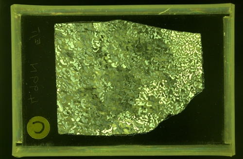
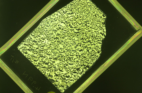
This polycrystal contains randomly oriented grains that allow transmission at different angles. Consequently different regions of the polycrystal are seen in these two photographs. (Click on the images to view larger versions.)
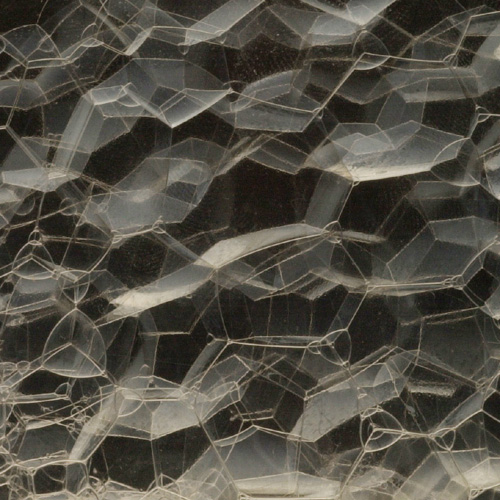
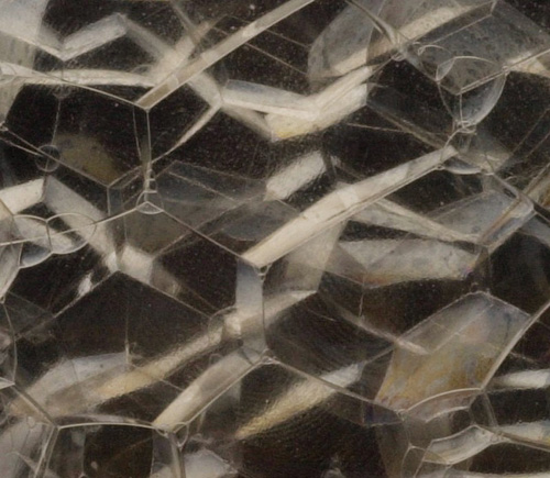
The three-dimensional shape of grains in a polycrystal is similar to the shape of individual soap bubbles made by blowing air into a soap solution contained in a transparent box.
The surface between bubbles is a high-energy feature. If the area of the surface is decreased, the overall energy of the system decreases, so reduction of surface area is a spontaneous process. If all the bubbles were the same size, the resulting structure would be a regular close-packed array, with 120° angles between the surfaces of neighbouring bubbles.
In practise, bubble growth can occur because the surface area of a few large bubbles is lower than that of many small bubbles. Large bubbles tend to grow, and small bubbles tend to shrink. The bubbles are therefore different sizes so there are large deviations from the close-packed structure. On average, however, three bubbles meet at a junction, and the angle between the bubble surfaces is usually within a few tens of degrees of 120°.
The curvature of the surfaces is also important. Surfaces with a smaller radius of curvature have a higher energy than those with a larger radius of curvature. As a result, some small bubbles cannot shrink and disappear, even though the surface area would decrease if they did so. This is because the curvature of the boundaries, and the associated energy, would be too high.
In a real polycrystal, the grain boundaries are high-energy features, similar to the surfaces between bubbles. The soap froth is a very good model for the grain structure of a simple polycrystalline material, and many similar features can be observed in the two systems. The soap bubbles are analogous to the grains, and the surfaces of the bubbles are analogous to the grain boundaries. Compare the photographs of the soap bubbles with the micrograph of a polycrystalline material that has been etched to reveal the grain boundaries.
 |
 |
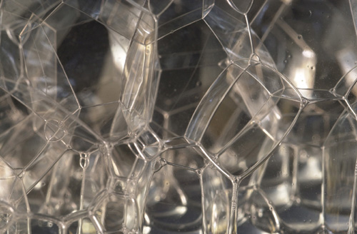 |
The packing of soap bubbles is somewhat similar to the packing of crystals - both systems seek to minimise their surface area. Note the angles at the junctions of grain boundaries. (Click on images to view larger versions.)
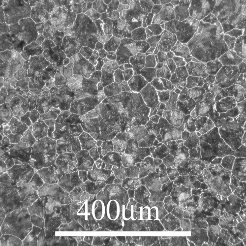
The grains of this hypereutectoid iron-carbon alloy are packed in a similar way to the bubbles in the previous photographs. (Click on image to view larger version.)
Grain boundaries in a polycrystalline solid can relax (move in such a way to decrease the total energy of the system) when atomic rearrangement by diffusion is possible. In real materials, many other effects can influence the observed grain structure.
Defects
Within a single crystal or grain, the crystal structure is not perfect. The structure contains defects such as vacancies, where an atom is missing altogether, and dislocations, where the perfection of the structure is disrupted along a line. Grain boundaries in polycrystals can be considered as two-dimensional defects in the perfect crystal lattice. Crystal defects are important in determining many material properties, such as the rate of atomic diffusion and mechanical strength.
We can use a "shot model" to get a picture of crystal defects. The model consists of many small ball bearings trapped in a single layer between two transparent plates. They tend to behave like the atoms in a crystal, and can show the same kind of defects.
When the shot model is held horizontally, so that the balls flow freely, the resulting structure is similar to a liquid.
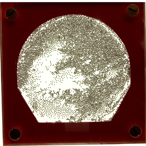
Shot model held horizontally. The balls form a liquid-like structure. (Click on image to view larger version.)
As the model is tilted towards the vertical, the balls pack closely together. This represents crystallisation. One or two balls may be suspended above the main body by electrostatic forces: this is comparable to the vapour found above the crystal.
In some places the balls form close-packed regions. Tapping of the model causes minor rearrangements of the balls, especially at the top of the "solid" region. This is similar to diffusion, in which case the tapping is analogous to thermal activation. Occasionally, the "diffusion" process may cause two grains to join together, or for some grains to "grow". The following image sequence shows the behaviour of the shot model as it is rearranged by tapping, starting from a polycrystalline state with many small grains and ending with much larger grains. Note the presence of vacancies in the structure.
Grain growth in the shot model
With great care, it may be possible to create a single crystal, as all the balls form a single pattern. Note that diffusion occurs mainly near the top of the balls: those towards the middle and bottom do not easily move, as the photographs show.
Even in a single crystal, or large-grained sample, there are still vacancies, as the shot model shows. The reason for this involves entropy: at all finite temperatures, there will be some disorder in the crystal.
The balls within a grain arrange themselves into close-packed planes. In metals, close-packing of atoms is a very common structure. This pattern is typical of hexagonal close-packed and cubic close-packed lattices. Note that in this 2-D model, each ball touches six others. In a 3-D crystal, such as a real one, each ball would also touch three on the plane above, and three on the plane below.
A close-packed plane.
In the shot model, the balls are normally arranged in to a polycrystalline form, shown schematically below:
A polycrystal will typically have crystalline regions (grains) bounded by disordered grain boundaries. These boundaries are marked in the picture on the right.
Note that the packing of atoms at the grain boundaries is disordered compared to the grains. At a grain boundary, the normal crystal structure is obviously disturbed, so the boundaries are regions of high energy. The ideal low energy state would be a single crystal.
Polycrystals form from a melt because crystallisation starts from a number of centres or nuclei. These developing crystals grow until they meet. Since they are not usually aligned before meeting, the grains need not necessarily be able to fit together as a single crystal, hence the polycrystalline structure.
After crystallisation the solid tends to reduce the boundary area, and hence the internal energy, by grain growth. This can only happen by a process of atomic diffusion within the solid. Such diffusion is more rapid at a higher temperature since it is thermally activated.
Summary
The focus of this package is the difference between single crystals, polycrystals and amorphous solids. This is explained in terms of the atomic scale periodicity: single crystals are periodic across their entire volume; polycrystals are periodic across individual grains; amorphous solids have little to no periodicity at all.
The different atomic structures can have effects on the macroscopic properties. A single crystal may exhibit anisotropy - we have seen mechanical anisotropy of gypsum, and optical anisotrpy of quartz. Polycrystals may also be anisotropic within each grain, as seen when the polycrystalline quartz-feldspar mix was placed between the crossed polarisers. Amorphous solids do not have anisotropic mechanical or optical properties, since they are isotropic on the atomic scale.
Defects may exist in all structures, even single crystals. They include vacancies and grain boundaries, where the regular repeating structure is disrupted.
Questions
Quick questions
You should be able to answer these questions without too much difficulty after studying this TLP. If not, then you should go through it again!
-
Most single crystals contain:
-
If quartz had optical properties such that the refractive indices for all vibration directions were equal, the crossed polariser experiment would show:
-
Bubbles in a box behave in a similar way to grains in a crystal in several ways, but not in all. Which of the following statements is TRUE?
-
Which of the following is false?
-
What does the 'shot model' fail to show?
Deeper questions
The following questions require some thought and reaching the answer may require you to think beyond the contents of this TLP.
-
Why is window glass transparent?
-
A quantity of pure liquid aluminium is cooled slowly through its melting point. The solid is then left at room temperature for 100 years. What is the resulting structure?
-
Self-diffusion is the diffusion of a species within a body of material made from the same species. In general, self-diffusion in a polycrystalline solid can occur through the bulk of the grains (lattice diffusion) or along the grain boundaries (grain boundary diffusion). Which of the following statements gives the best description of the relative contribution of each process to the overall diffusion rate?
-
Imagine a polycrystalline solid with cubic grains of edge length D. When D = 10 μm, what percentage of the volume of solid lies within a grain boundary, if the grain boundary width d is 1 nm? What must the grain size D be if 10% of the volume lies within a grain boundary? Comment on your answers.
-
Which of the following material properties could show anisotropy? (answer yes or no for each)
Open-ended questions
The following questions are not provided with answers, but intended to provide food for thought and points for further discussion with other students and teachers.
-
Think about some of the possible applications of materials showing optical anisotropy, like the quartz crystal.
-
How might you control the grain size of a material produced from a melt? How might the cooling rate and the chemical composition affect the results? Can you think of ways to change the grain structure after the material has solidified?
-
In this TLP, we have discussed pure materials. Real materials almost always contain some impurities. How might these impurities be incorporated into the crystal structure of a material? Consider the relative size of the impurity atoms and the host atoms. Are impurities always undesirable?
-
Graphite is sometimes used as a lubricant, and diamond can be used on the tips of cutting tools. In terms of the crystal structure, why might this be?
-
Why do the individual grains in a polycrystalline material, such as those in the photo of galvanised steel (on the Polycrystals page) appear to be different colours or shades, when the composition of every grain is approximately the same?
Going further
Most 'introductory' materials science textbooks will cover the basic material in this package. The following resources cover the subjects in more detail than this teaching and learning package, and may prove useful to the interested student.
Books
Introduction to Mineral Sciences by Putnis (Cambridge University Press, 1992)
Provides a mineral-based treatment of many of the topics introduced in this package. Of particular interest:
Chapter 1 on Periodicity and Symmetry
Chapter 2 on Anisotropy and Optical Properties, including the phenomenon of birefringence
Chapter 5 on Crystal Structures
Chapter 7 on Defects in Minerals
The Structure of Materials by Allen and Thomas (Wiley, 1999)
Gives a thorough mathematical treatment of the noncrystalline and crystalline states (chapters 2 and 3).
Websites
- Steffen Weber's homepage
Contains java-based applets that allow the structure of common polyhedra and crystals to be explored. - Crystallography and Minerals Arranged by Crystal Form
A library of 'crystal forms' - the shapes adopted by natural crystals. Contains Java applets. - Molecular Expressions:
Optical Birefringence
An excellent tutorial on birefringence. Contains Java applets.
Other resources
The MATTER Project's 'Materials Science on CD-ROM' includes modules on:
Introduction to Crystallography (including Miller Indices etc.)
Introduction to Point Defects
Dislocations
Birefringence
Light waves have a magnetic component and an electric component, as all electromagnetic waves do. These are mutually perpendicular, and extend perpendicular to the line of travel. Generally, light will be composed of randomly oriented waves. However, when it is passed through a polariser, the polarisations will all be resolved into one direction.
When the polarised light meets the second polariser (the analyser), it will again be resolved into that direction of polarisation. However, since the analyser is set at 90° to the first polariser, it should let nothing through whatsoever. With no sample between the polariser and analyser, no light is transmitted.
No light is normally transmitted across the crossed polarisers.
Glass, being isotropic, will have no effect on the polarisation of the light passing through it. Quartz has a crystal with a trigonal unit cell, and as such, it has unique properties along its c-axis. (a = b ¹ c, α = β = 90º, γ = 120º)
Trigonal unit cell with a = b ¹ c, α = β = 90º, γ = 120º
The refractive index for light travelling along the 'a' or 'b' axes (no) is 1.544; that for light travelling along the 'c' axis (ne) is 1.553. Light travelling through the crystal along any direction except [001] will encounter two refractive indices. It therefore splits into two parts: one part is resolved onto an ordinary direction; the other is resolved onto an extraordinary direction. These parts will travel at different speeds due to their different refractive indices. When the light emerges from the crystal, the overall wave is different from that which went in, and there is now some component of the wave parallel to the analyser. Some light may now pass through the analyser, as observed.
An optically anisotropic sample may rotate the polarisation of the light, allowing some transmission.
There is a special case of this, in which the light travels along [001]. In this situation, only one refractive index is encountered (ne), so the light all goes through at the same speed with its polarisation unchanged. No light would therefore be transmitted through the analyser.
Even in the case of light travelling along a direction not parallel to [001], the quartz may be rotated so that the light emerging from it is exactly perpendicular to the analyser's polarisation direction. No light will be transmitted, as before. This explains why the intensity of transmitted light varied from zero to some maximum when the quartz was rotated. The minima appear at 90º intervals, being the angle between the c-axis and the other axis. This is observed in the animation above.
Academic consultant: John Leake (University of Cambridge)
Content development: Derek Holmes and Ashleigh Bridges
Photography and video: Brian Barber and Carol Best
Web development: Dave Hudson
This TLP was prepared when DoITPoMS was funded by the Higher Education Funding Council for England (HEFCE) and the Department for Employment and Learning (DEL) under the Fund for the Development of Teaching and Learning (FDTL).
Additional support for the development of this TLP came from the Armourers and Brasiers' Company and Alcan.