Finding the principal stress tensor
Rotating the axes:
The principal stresses are the eigenvalues of the stress tensor. These can be found from the determinant equation:
$$\left| {\begin{array}{*{20}{c}} {{\sigma _{11}} - \xi }&{{\sigma _{12}}}&{{\sigma _{13}}}\\ {{\sigma _{21}}}&{{\sigma _{22}} - \xi }&{{\sigma _{23}}}\\ {{\sigma _{31}}}&{{\sigma _{32}}}&{{\sigma _{33}} - \xi } \end{array}} \right| = 0$$
This determinant is expanded out to produce a cubic equation from which the three possible values of \(\xi \) can be found; these values are the principal stresses. This is discussed in the book by J.F. Nye [1].
If the stress tensor already has a principal stress along one axis, such as σ33, diagonalising is much simpler:
$$\left| {\begin{array}{*{20}{c}} {{\sigma _{11}} - \xi }&{{\sigma _{12}}}&0\\ {{\sigma _{21}}}&{{\sigma _{22}} - \xi }&0\\ 0&0&{{\sigma _{33}} - \xi } \end{array}} \right| = 0$$
When we expand this out, we find that:
\[({\sigma _{33}} - \xi )\left[ {({\sigma _{11}} - \xi )({\sigma _{22}} - \xi ) - \sigma _{12}^2} \right] = 0\]
One of the principal stresses must be σ33, and the other two are easy to find by solving the quadratic equation inside the square brackets for \(\xi \). Alternatively, when there are only two principal stresses to find, such as in this example, we can use Mohr’s circle.
![]()
Mohr’s circle method:
Mohr’s circle in this situation represents a stress state, on two axes – normal (σ) and shear (τ). A Mohr's circle drawn according to the convention in Gere and Timoshenko [4] in shown below.
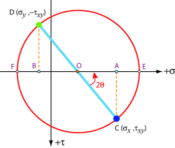
The normal stresses σx and σy are first plotted on the horizontal σ axis at A and B. Positions C and D are then generated using the magnitude of the shear stress τxy, with the convention for the choice of these positions shown. Different orientations of the axes, and the different stress tensors produced by them, are represented by the different diameters it is possible to take of the circle.
The principal stress state is the state which has no shear components. This corresponds to the diameter of the Mohr’s circle that has no component along the shear axis – it is the diameter that runs along the normal stress axis. The principal stresses are thus the two points where the circle crosses the normal stress axis, E and F:
$$\left( {\begin{array}{*{20}{c}} E&0&0\\ 0&F&0\\ 0&0&{{\sigma _3}} \end{array}} \right)$$
The angle 2θ shown on the Mohr's circle in an anti-clockwise sense is twice the angle θ required to rotate the set of axes in an anti-clockwise sense from the old set of axes to the principal axes with respect to which the principal stresses are defined.
The Mohr’s circle below is for an element under a stress state of σ11 = 80 MPa, σ22 = – 60 MPa, σ12 = 50 MPa and σ3 = 100 MPa. Using the slider, change its inclination angle and compare it to the tensor representing the stress state.
Given below is an interactive tool to plot a Mohr's circle according to user's specified stress states.