Ferroelectric Materials (all content)
Note: DoITPoMS Teaching and Learning Packages are intended to be used interactively at a computer! This print-friendly version of the TLP is provided for convenience, but does not display all the content of the TLP. For example, any video clips and answers to questions are missing. The formatting (page breaks, etc) of the printed version is unpredictable and highly dependent on your browser.
Contents
Main pages
Additional pages
Aims
After completing this TLP, you should:
- Be aware of the atomic requirements for ferroelectricity.
- Understand how this atomic structure leads to spontaneous polarisation, and how this polarisation can be switched.
- Understand how this polarisation leads to the interesting electrical properties displayed by ferroelectrics.
- Understand how these properties are made use of in today's technologies.
Before you start
This TLP should be fairly self-contained, but some knowledge of crystal structures is assumed. It may be helpful to read the teaching and learning package on Crystallography and Atomic Scale Structure Of Materials first.
Introduction
The ferroelectric effect was first observed by Valasek in 1921, in the Rochelle salt. This has molecular formula KNaC4H4O6·4H2O. The effect was then not considered for some time, and it wasn't until a few decades later that ferroelectrics came into great use. Nowadays, ferroelectric materials are used widely, mainly in memory applications. This TLP will show how the ferroelectric effect arises, and how it is usefully used.
The dipole moment
To be ferroelectric, a material must possess a spontaneous dipole moment that can be switched in an applied electric field, i.e. spontaneous switchable polarisation. This is found when two particles of charge q are separated by some distance r, i.e.:
The dipole moment, μ is:
μ = q.r
In a ferroelectric material, there is a net permanent dipole moment, which comes from the vector sum of dipole moments in each unit cell, Σμ. This means that it cannot exist in a structure that has a centre of symmetry, as any dipole moment generated in one direction would be forced by symmetry to be zero. Therefore, ferroelectrics must be non-centrosymmetric. This is not the only requirement however. There must also be a spontaneous local dipole moment (which typically leads to a macroscopic polarisation, but not necessarily if there are domains that cancel completely). This means that the central atom must be in a non-equilibrium position. For example, consider an atom in a tetrahedral interstice.
In (A) the structure is said to be non-polar. There is no displacement of the
central atom, and no net dipole moment. In (B) however, the central atom is
displaced and the structure is polar. There is now an inherent dipole moment
in the structure. This results in a polarisation.
Polarisation
Polarisation may be defined as the total dipole moment per unit volume, i.e.
\[P = \frac{{\sum \mu }}{V}\]
Materials are polarised along a unique crystallographic direction, in that certain atoms are displaced along this axis, leading to a dipole moment along it. Depending on the crystal system, there may be few or many possible axes. As it is the most common and easy to see, let us examine a tetragonal system that forms when cooled from the high temperature cubic phase, through the Curie temperature, of e.g. Tc=120°C in BaTiO3.
In this system, the dipole moment can lie in 6 possible directions corresponding to the original cubic axes:
In a crystal, it is likely that dipole moments of the unit cells in one region lie along a different one of the six directions to the dipole moments in another region. Each of these regions is called a domain, and a cross section through a crystal can look like this:
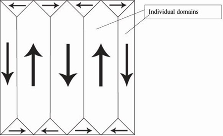
A domain is a homogenous region of a ferroelectric, in which all of the dipole moments in adjacent unit cells have the same orientation. In a newly-grown single crystal, there will be many domains, with individual polarisations such that there is no overall polarisation. They often appear:
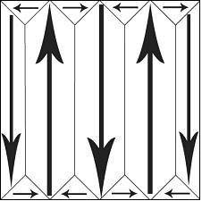
The polarisation of individual domains is organised such that +ve heads are held near -ve tails. This leads to a reduction in stray field energy, because there are fewer isolated heads and tails of domains. This is analogous to the strain energy reduction found in dislocation stacking.
Domain boundaries are arranged so that the dipole moments of individual domains meet at either 90°or 180°. In a polycrystal (one with more than one crystallographic grain), the arrangement of domains depends on grain size. If the grains are fine (<< 1 micron), then there is usually found to be one domain per grain. In larger grains there can be more than one domain in each grain.
This is a micrograph showing the domains in a single grain.
This micrograph is reproduced from the DoITPoMS
Micrograph Library (entry number: 199).
In this grain, the domains are twinned in such a way as to reduce the overall
stray electric field energy. As each domain possesses its own dipole moment,
we may switch dipole moments in order to encode information.
Switching polarisation (1)
In an electric field, E, a polarised material lowers its (volume-normalized) free energy by –P.E, (where P is the polarisation). Any dipole moments which lie parallel to the electric field are lowered in free energy, while moments that lie perpendicular to the field are higher in free energy and moments that lie anti-parallel are even higher in free energy, (+P.E).
This introduces a driving force to minimise the free energy, such that all dipole moments align with the electric field.
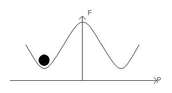
Let us start by considering how dipole moments may align in zero applied field:
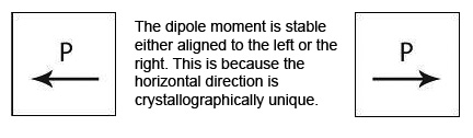
These two moments are stable, because they sit in potential energy wells. The potential barrier between them can be represented on a free energy diagram:
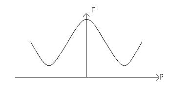
This material is considered to be homogenous. If the polarisation points left then we have:
The electric field alters the free energy profile, resulting in a ‘tilting’ of the potential well:
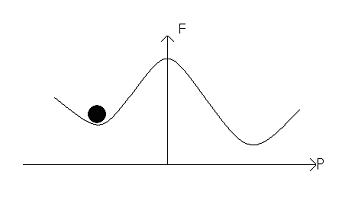
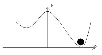
An increase in the electric field will result in a greater tilt, and lead to the dipole moments switching, leading to:
Next we must look at the more realistic scenario in which domains form.
Switching polarisation (2)
Consider a material which is fully polarised, so that all of the dipole moments are aligned in the same direction. Then apply a reversed electric field over it. New domains with a reversed polarisation nucleate at the electrodes. They then grow towards the other electrode, forming needle domains. When they reach the other electrode, they then grow laterally until the polarization of the entire sample is reversed.
This shows the origin of the hysteresis loop. The removal of the field will leave some polarisation behind, and only when the field is reversed does the polarisation start to lessen as new, oppositely poled domains form. They grow quickly however, giving a large change of polarisation for very little electric field. But to form an entirely reversed material, a large switching field is required. This is because of both defects in the crystal structure, in a manner similar to zener drag, and also to do with stray field energy. The polarisation of the material goes from a coupled pattern, with 180° boundaries, to a state in which many heads and tails are separated. This leads to the increase in stray field energy. Therefore, to attain this state, lots of energy has to be put in by a larger field.
Here we show a how a minor hysteresis loop fits into the major loop above.
The part of curve shown fits into the major hysteresis curve.
There are three sections to this curve.
1) Reversible domain wall motion.
2) Linear growth of new domains.
3) New domains reaching the limit of their growth.
Measurement of polarisation
Polarisation may be defined as:
\[P = \frac{Q}{A}\] where Q is the charge developed on the plates (Coulombs) and A is the area of the plates (m2).
A good ferroelectric has 10 μC cm-2 < P < 100 μC cm-2.
We can measure the polarisation by using the classic Sawyer-Tower circuit:
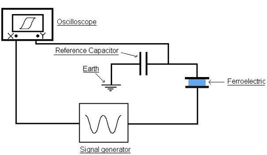
In this experiment, the voltage is cycled by the signal generator. Its direction is reversed at high frequency, and the voltage across the reference capacitor is measured. The charge on the capacitor must be the same as the charge over the ferroelectric capacitor, as they are in series. This means the charge on the ferroelectric can be found by:
Q = C × V
where C is the capacitance of the reference capacitor, and V is the voltage measured over this capacitor. We can therefore represent the polarisation of a material in an oscillating electric field, by plotting the voltage applied to the material on the x-axis of the oscilloscope, and the surface charge on the y-axis. This can be done because the capacitance of the reference capacitor is much higher than the capacitance of the ferroelectric, so most of the voltage lies over the ferroelectric. It is only possible to measure P by cycling the polarisation through cycling the voltage across the ferroelectric. We cannot measure absolute values instantaneously , but can deduce absolute values from the changes measured when cycling the polarisation.
Fabrication of a KNO3 ferroelectric capacitor
A capacitor can be made from potassium nitrate (KNO3), which is ferroelectric below 120°C. (The temperature dependence of ferroelectrics will be explained later.) The following video clip shows the construction of a KNO3 capacitor, and the hysteresis loop it displays. The circuit used is the standard Sawyer-Tower circuit.
Demonstration to construct a KNO3 capacitor
The result is a hysteresis loop. This arises from the fact that a system does not respond immediately to a given set of external conditions. Rather, there is a history dependence and this is the basis for memory (two states are possible in E=0).
The final hysteresis loop appears like this:
When the field is removed, the polarisation does not disappear like a dielectric.
(a→ c). The polarisation which remains after a material has been fully
polarised and then had the field removed is called the remanent polarisation
(Pr).
Only after a field is applied in the opposite direction to the original polarising
field does the polarisation diminish significantly. There is a specific field
which results in zero net polarisation (d). This is called the coercive field
(EC).
Finally, if a sufficiently strong electric field is applied in the reverse direction,
the polarisation will reach its maximum value in the opposite direction (e).
To understand how the polarisation switches we must consider domains more fully.
Temperature dependence of the Hysteresis loop
We have now seen the way in which the hysteresis loop arises. However, there are more aspects to the hysteresis loop.
We have only observed it at one particular temperature, one at which the material is ferroelectric. What happens if the temperature is raised? The hysteresis loop changes with temperature, becoming sharper and thinner, and eventually disappearing, i.e.:
As you can see, the polarisation increases at 90°C, as a result of a phase transition. Between this temperature and room temperature, the polarisation increases steadily, as a direct relation with temperature, such that:
ΔP = p ΔT
where p = pyroelectric coefficient (C m-2 T-1).
Why should this be?
This is a general behaviour (that does not apply to KNO3) that can arise for
two reasons depending on the material.
- Disorder. Each unit cell has its own dipole moment, which, when there is a net polarisation, are described as ordered. At high T, the direction of the dipole moments randomises, giving a disordered material with no net polarisation.
- Phase transitions that can open up new possibilities for dipole moments
to form. In this case, there is a jump at 0°C, and at 90°C, where
the loop becomes taller.
Barium titanate
Let us consider one of the most well-known ferroelectrics, barium titanate, (BaTiO3).
It has this perovskite structure:
Barium titanate and phase changes
The temperature at which the spontaneous polarisation disappears is called the Curie temperature, TC.
Above 120°C, barium titanate has a cubic structure. It is therefore centro-symmetric and possesses no spontaneous dipole. With no spontaneous dipole the material behaves like a simple dielectric, such that its polarisation varies linearly with field. TC for barium titanate is 120°C.
Below 120°C, it changes to a tetragonal phase, with an accompanying movement of the atoms. The movement of Ti atoms inside the O6 octahedra may be considered to be significantly responsible for the dipole moment:
Cooling through 120°C causes the cubic phase of barium titanate to transform to a tetragonal phase with the lengthening of the c lattice parameter (and a corresponding reduction in a and b). The dipole moment may be considered to arise primarily due to the movement of Ti atoms with respect to the O atoms in the same plane, but the movement of the other O atoms (i.e. those O atoms above and below Ti atoms) and the Ba atoms is also relevant.
The diagram below shows the BaTiO3 structure with an O6 octahedron surrounding the Ti atom.
The switching to a cubic structure is the reason for the polarisation spontaneously disappearing above 120°C. Barium titanate has two other phase transitions on cooling further, each of which enhances the dipole moment:
The phase which is reached after cooling to ~ 0°C from tetragonal is orthorhombic.
And then rhombohedral below -90°C:
All of these ferroelectric phases have a spontaneous polarisation based to a significant extent on movement of the Ti atom in the O6 octahedra in the following way (using pseudo-cubic notation):
Order of phase transitions
Two common types of phase transition may be identified. These are named depending on how the order changes during the transition. In ferroelectrics this is the polarisation, which is called the order parameter. A first order transition is one which has a discontinuity in the order parameter itself, while a second order transition is one which has a discontinuity in the first derivative of the order parameter. Plots of the spontaneous polarisation vs. temperature appear as follows.
First order |
Second order |
 |
 |
In a first order transition the polarisation varies continuously, until the Curie temperature at which there is a discontinuity. In a second order transition, the order parameter itself is a continuous function of temperature, but there is a discontinuity in its first derivative at TC.
Ferroelectrics - why?
Ferroelectric materials are used for binary information storage in FeRAM (Ferroelectric Random Access Memory). The zeroes and ones in each ferroelectric capacitor correspond to a polarization that is up or down. The polarization state is set up or down by applying a positive or negative voltage, and the polarization stays up or down after removing this voltage. FeRAM therefore offers non-volatile data storage. However, to read FeRAM data, the polarization must be electrically cycled, which takes time and erases the data (destructive read).
FeRAM was used in the Sony Playstation 2, and it has also been used in smart cards for Japanese railways.
Summary
Ferroelectrics have now been in use for decades, but they are still an expanding field. Their use in computing will only increase as they are miniaturised. However, to do this, the way in which their properties vary on the microscale has to be understood, so this will be a target for future research. Ferroelectrics will be used for a long time to come, as their properties are unique.
Questions
Quick questions
You should be able to answer these questions without too much difficulty after studying this TLP. If not, then you should go through it again!
-
What symmetry element must be absent for a material to be ferroelectric?
-
Which of these is not a correct definition of polarisation?
-
Why are domains in crystals found in a manner such that their polarisation is coupled?
-
What is needed to make ferroelectric domains useful as a binary memory store?
-
If a ferroelectric, 50mm by 10 mm, has a measured surface charge of 2.5 x 10⁻⁴ Coulombs, and a lattice parameter of 5 x 10⁻¹⁰ m, what is the dipole moment in a single cubic unit cell?
-
What field has to be applied to give a ferroelectric, with a square hysteresis loop, zero net polarisation?
Going further
Books
- Ferroelectrics: An Introduction to the Physical Principles by J.C. Burfoot, D. Van Nostrand Company Ltd., 1967
Websites
- You may wish to look at the related TLP on Piezoelectric
Materials.
Construction of a KNO3 capacitor (loop)
Demonstration to construct a KNO3 capacitor
Academic consultant: Neil Mathur (University of Cambridge)
Content development: Robert Shaw
Video: Department of Earth Sciences, University of Cambridge
Web development: Lianne Sallows
This DoITPoMS TLP was funded by the UK Centre for Materials Education and the Department of Materials Science and Metallurgy, University of Cambridge.
Additional support for the development of this TLP came from the Worshipful Company of Armourers and Brasiers'