Worked examples
Example A
The figure below is a scanning electron micrograph of a niobium carbide dendrite in a Fe-34wt%Cr-5wt%Nb-4.5wt%C alloy. Niobium carbide has a face centred cubic lattice. The specimen has been deep-etched to remove the surrounding matrix chemically and reveal the dendrite. The dendrite has 3 sets of "arms" which are orthogonal to one another (one set pointing out of the plane of the image, the other two sets, to a good approximation, lying in the plane of the image), and each arm has a pyramidal shape at its end. It is known that the crystallographic directions along the dendrite arms correspond to the < 100 > lattice directions, and that the direction ab labelled on the micrograph is [10].
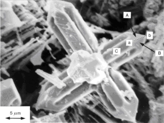
sourced from Dendritic Solidification
1) If point c (not shown) lies on the axis of this dendrite arm, what is the direction cb ? Index face C , marked on the micrograph.
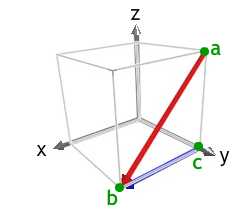
The diagram shows the [10] direction in red. The [100] direction is a < 100 > type direction that forms the observed acute angle with ab, and can be used as cb. Of the < 100 > type directions, we could also have used [00].
Using a right handed set of axes, we then have z-axis pointing out of the plane of the image, the x-axis pointing along the direction cb, and the y-axis pointing towards the top left of the image.
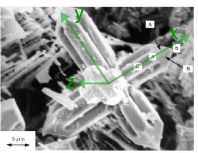
Face C must contain the direction cb, and its normal must point out of the plane of the image. Therefore face C is a (001) plane.
2) The four faces which lie at the end of each dendrite arm have normals which all make the same angle with the direction of the arm. Observing that faces A and B marked on the micrograph both contain the direction ab , and noting the general directions along which the normals to these faces point, index faces A and B .
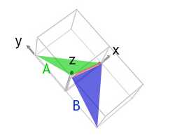
Both faces A and B have normals pointing in the positive x and z directions, i.e. positive h and l indices. Face A has a positive k index, and face B has a negative k index.
The morphology of the ends of the arms is that of half an octahedron, suggesting that the faces are (111) type planes. This would make face A, in green, a (111) plane, and face B, in blue, a (11) plane. As required, they both contain the [10] direction, in red.
Example B
1) Work out the common direction between the (111) and (001) in a triclinic unit cell.
The relation derived from the Weiss zone law in the section Vectors and planes states that:
The direction, [UVW], of the intersection of (h1k1l1) and (h2k2l2) is given by:
U = k1l2 − k2l1
V = l1h2 − l2h1
W = h1k2 − h2k1
We can use this relation as it applies to all crystal systems, including the triclinic system that we are considering.
We have h1 = 1, k1 = 1, l1 = 1
and h2 = 0, k2 = 0, l2 = 1
Therefore
U = (1 × 1) - (0 × 1) = 1
V = (1 × 0) - (1 × 1) = −1
W = (1 × 0) - (0 × 1) = 0.
So the common direction is:
[10].
This is shown in the image below:
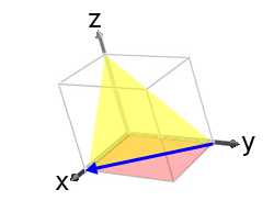
If we had defined the (001) plane as (h1k1l1) and the (110) plane as (h2k2l2) then the resulting direction would have been, [10] i.e. anti-parallel to [10].
2) Use the Weiss zone law to show that the direction [10] lies in the (111) plane.
We have U = 1, V = −1, W = 0,
and h = 1, k = 1, l = 1.
hU + kV + lW = (1 × 1) + (1 × −1) + (1 × 0) = 0
Therefore the direction [10] lies in the plane (111).