Casting (all content)
Note: DoITPoMS Teaching and Learning Packages are intended to be used interactively at a computer! This print-friendly version of the TLP is provided for convenience, but does not display all the content of the TLP. For example, any video clips and answers to questions are missing. The formatting (page breaks, etc) of the printed version is unpredictable and highly dependent on your browser.
Contents
Main pages
Additional pages
Aims
On completion of this TLP you should:
- Understand the meaning of the Biot number, how it affects the temperature profile in a casting, and the resulting microstructure.
- Be able to explain the formation of the microstructure observed in a cast ingot.
- Be familiar with some common methods of casting, their advantages and disadvantages, and be able to choose a suitable process for manufacturing a variety of metallic components.
Before you start
It will be helpful to have an understanding of solute partitioning and the formation of dendrites. The TLP on Solidification of Alloys covers these topics.
Introduction
Casting processes are essential in forming solid ingots or billets of metals for further processing, but moreover, a wide variety of casting processes are used in the production of finished or semi-finished components. Casting allows the production of complex shapes, without the need to introduce weaknesses when joining separate pieces, and is conservative of material compared with machining or cutting a shape from a large piece of metal. The methods available can achieve various standards of surface finish, microstructure, start-up cost, unit cost, and production volume, in order to suit many applications.
Heat transfer
The rate of solidification of a metal during casting is dictated by;
- The excess heat in the liquid metal on pouring,
- The amount of heat produced by the solidification of the metal (the latent heat of fusion),
- The rate at which this heat can be dissipated from the metal.
A simple way to predict the way in which a casting will solidify, is using the Biot number, Bi, given by:
\[Bi = \frac{h}{K / L}\]
where h is the heat transfer coefficient between the metal and the mould wall, K/L is the thermal conductance of the casting, calculated from K, the thermal conductivity of the liquid metal, and L, the length of the casting in the direction of the heat flow.
When the Biot number is large, heat is transferred quickly from the metal to the mould, but takes longer to reach the mould wall from the centre of the casting, resulting in a significant temperature gradient in the casting, and only a small temperature difference across the interface.
When the Biot number is small, the transfer of heat to the edge of the casting is faster than the transfer of heat from the metal to the mould, resulting in a large temperature difference across the interface, and only a small temperature gradient within the casting. This is illustrated in the movie below:
For the situation where Bi << 1, we can consider the cooling and solidification separately.
Firstly, the liquid metal cools uniformly from its pouring temperature, Tp, to its melting temperature, Tm We know that:
q = hΔT
and
\[q = \frac{{dT}}{{dt}}{C_V}L\]
so that
\[\frac{{{\rm{d}}T}}{{{\rm{d}}t}} = \frac{{h\Delta T}}{{L{C_V}}}\]
where dT / dt is the cooling rate, and CV, is the heat capacity of the liquid.
The time, tC, taken for the casting to reach Tm is given by:
\[{t_C} = \frac{{L{C_V}}}{h}\ln \left| {\frac{{{T_W} - {T_M}}}{{{T_W} - {T_P}}}} \right|\]
where TW is the temperature of the mould wall. To see how this is derived click here.
The solidification stage can be understood by equating the heat transferred across the interface, with the heat generated by the solidification:
q = hΔT
q = vΔHF
so that
\[v = \frac{{h\Delta T}}{{\Delta {H_F}}}\]
where v is the speed of the solidification front, and ΔHF is the latent heat of fusion of the metal.
The time, tS, taken for the metal to solidify once it has reached Tm is given by:
\[{t_S} = \frac{{\Delta {H_F}L}}{{h({T_W} - {T_M})}}\]
The total time taken for the casting to solidify once the metal has been poured in is:
\[t = \frac{L}{h}\left( {{C_V}\ln \left| {\frac{{{T_W} - {T_M}}}{{{T_W} - {T_P}}}} \right| - \frac{{\Delta {H_F}}}{{\left( {{T_W} - {T_M}} \right)}}} \right)\]
Heat transfer simulation
Here we demonstrate how heat transfer through the mould wall determines the temperature change in a casting during solidification. The simulation assumes Newtonian cooling where heat transfer is limited by the interface between the metal and the mould.
The simulation shows the effect of varying parameters such as the interfacial heat transfer coefficient, h, the casting length, L and the amount of superheat (determined by the pouring temperature, Tp). It can be carried out for a wide range of metals to study the effect of properties such melting temperature Tm, latent heat of fusion per unit volume, ΔHf,V, thermal conductivity, K and heat capacity per unit volume, Cp,V. Click here to see how the heat capacity per unit volume is related to specific heats measured relative to other amounts.
The relevant thermal properties of several pure metals are shown below
Melting temperature |
Latent Heat of fusion |
Volumetric Heat capacity |
Thermal conductivity |
|
K |
MJ m-3 |
kJ m-3 K-1 |
W m-1 K-1 |
|
Ag |
1235 |
1100 |
2920 |
422 |
Au |
1337 |
1200 |
2800 |
272 |
Al |
933 |
1070 |
3100 |
240 |
Cu |
1358 |
1842 |
4080 |
395 |
Mg |
922 |
640 |
2240 |
154 |
Pb |
601 |
260 |
1590 |
34 |
Sn |
505 |
440 |
1780 |
63 |
Zn |
693 |
812 |
3070 |
112 |
In the simulation you can select any of these materials and its properties will be displayed. You may then vary parameters such as the casting length, the interfacial heat transfer coefficient between the solid and the mould wall and the pouring temperature in order to see how long it takes for the casting to solidify and cool.
There are a couple of provisos: Firstly because this is a Newtonian cooling simulation you must ensure that the Biot number is low enough for this assumption to be valid (hence for the metals which have poor thermal conductivities, you must keep the casting length relatively low). Secondly, of course, you must ensure that the metal is poured above its melting temperature!
There are a number of assumptions and simplifications we are making in this simulation which may not be the case for a real casting.
Microstructure and segregation in castings
Microstructure of castings
The animation below shows how the microstructure of an ingot develops during solidification.
For a closer look at dendrite formation look at this animation in the Solidification of alloys TLP.
Below is a picture of a real cast Al ingot. Move your mouse over the various parts to see how they are formed.
Segregation in castings
When casting an alloy, segregation occurs, whereby the concentration of solute is not constant throughout the casting. This can be caused by a variety of processes, which can be classified into two types:
Microsegregation; which occurs over distances comparable to the size of the dendrite arm spacing. This occurs as a result of the first solid formed being of a lower concentration than the final equilibrium concentration, resulting in partitioning of the excess solute into the liquid, so that solid formed later has a higher concentration. More about microsegregation can be found in the TLP on Solidification of alloys.
Macrosegregation occurs over similar distances to the size of the casting. This can be caused by a number of complex processes involving shrinkage effects as the casting solidifies, and a variation in the density of the liquid as solute is partitioned. We will not discuss these processes further.
It is desirable to prevent segregation during casting, to give a solid billet that has uniform properties throughout. Microsegregation effects can be removed after casting, by homogenisation, carried out at by annealing at high temperatures where the diffusivity is higher. Macrosegregation effects occur over larger distances so cannot be removed in this way, but can be reduced by control of the casting process and mixing during solidification, often by electromagnetic stirrers. Ultrasound is sometimes used to break up dendrites as they grow, reducing the scale of the dendritic structure and the extent of microsegregation.
Sand casting
Sand castings are formed using compacted sand as the mould, more details of the process can be found in the movie below:
Typical components produced by sand casting are automobile engine blocks and ship propellers.
Advantages:
- Low capital investment means that short production runs are viable.
- Use of sand cores allows fairly complex shapes to be cast.
- Large components can be produced.
Disadvantages:
- The process has a high unit cost, as it is labour intensive and time consuming.
- The sand mould leaves a poor surface finish, which often requires further processing.
- Cannot make thin sections.
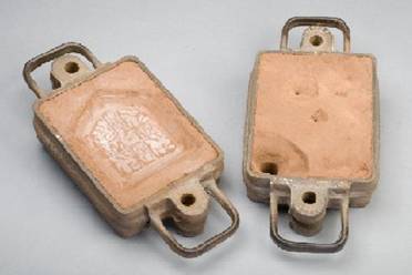
The drag (left) and cope (right) of a casting flask
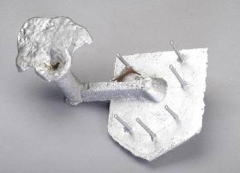
A sand casting with risers and the runner system still attached
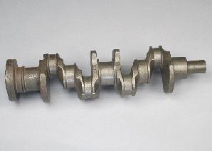
A crankshaft for an auto engine which has been produced by sand casting
Different types of sand are used in sand casting;
- Petro-bond – This is a mixture of quality sand and oil or synthetic resin.
- Green sand – A mixture of sand, clay, water and sometimes other additives. It is called green sand because it is re-usable. The right amount of water has to be added to prevent porosity.
- Sand mixed with water glass (NaO.nSiO2.mH2O) can be hardened with CO2 gas through the chemical reaction;
Na2O.nSiO2.(mn + x)H2O + CO2 = Na2CO3.xH2O + n(SiO2.mH2O)
This transforms the sand into a solid mould, which can be used after the cope & drag are removed. - A parting powder similar to talcum powder is put on the pattern to make it easier to remove.
More complicated castings can be made by producing a pattern out of polystyrene foam, which is left in place when the molten metal is added. When the metal is poured into the mould the heat vaporizes the foam a short distance away from the metal surface, allowing the metal to fill the mould cavity.
Permanent Mould casting
The basic process of permanent mould casting is similar to that for sand casting, except that a permanent metallic mould is used. This mould is made of two parts, containing the necessary gates and risers to ensure the correct flow of metal. The metal moulds give a better surface finish than sand casting, and selective cooling rates can give control over the scale and morphology of microstructure formed.
Die casting
Die casting is an automated process that forms castings under high pressure in a metal mould. More details of the process can be found in the movie below:
Typical items produced by die casting are toys and small precision parts such as sprockets and gears.
Aluminium, copper and zinc alloys are commonly used in die casting, ferrous alloys are harder to cast in this way as the moulds are made from hardened steel.
There are various methods of die casting;
- Gravity fed – Similar to permanent mould casting, the material is poured into the top of the mould & forced downwards by gravity.
- Pressure – The metal is forced into the mould under pressure.
- Cold chamber – Molten metal is poured into the system and then forced into the mould.
- Hot chamber – The metal is heated within the system & then forced from the crucible into the die.
- Squeeze – Similar to injection moulding, a given amount of material is forced into the mould.
Advantages:
- Very low unit cost.
- High definition & surface finish.
- Excellent dimensional accuracy.
- Cool metal mould gives fast solidification, leading to a fine grain structure.
- Can produce thin sections.
Disadvantages:
- A large capital investment is required to set up a die casting process.
- It is difficult to control the microstructure of the solid.
- The alloys used must have a low melting point, often at the expense of other properties, such as strength and stiffness.
- Cannot be used for complex shapes, as the casting couldn’t be ejected from the mould.
- Cannot be used for large castings.
Continuous casting
Continuous casting is used to produce very large quantities of metals in simple shapes, by casting & rolling the metal continuously in one process. The slabs are then generally further processed by methods such as rolling, extrusion or another casting method to make more useful items.
More about process methods can be found in the TLP on Metal Forming – Introduction to Deformation Processes.
Advantages:
- High yield of casting for a given volume of liquid, mainly thanks to the lack of a contraction pipe.
- Good surface finish.
- Extremely low unit cost due to the very high volume of metal that can be cast.
Disadvantages:
- A large capital investment is required to set up the process.
- Only simple shapes can be cast, which must have a constant cross-section.
Investment casting
Investment casting is used to make precision parts with a good surface finish. It is used to make turbine blades from a single crystal Ni-based superalloys. As the moulds are made from ceramic, metals with high melting points can be cast in this way.
- A pattern of the required component is formed out of wax usually through injection moulding into a metal mould. A runner and gate are included within the wax pattern. Pre formed ceramic cores can also be added, so that hollow castings can be made.
- Many wax patterns are then connected together to form a tree, and this is then dipped into a ceramic slurry, which sets through drying. Different layers of ceramic are created around the wax patterns, increasing in coarseness.
- The wax patterns are then melted out, ready for the molten metal to be poured in to create the castings.
- The ceramic mould is broken to reveal the castings, and any ceramic cores added at the start can be chemically etched out to leave a hollow structure.
 |
 |
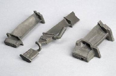 |
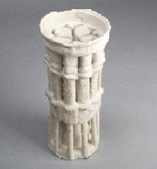
| Investment wax | Investment mould | Investment blades |
Video of investment casting
Advantages
- Metals with a high melting temperature can be cast due to ceramic mould
- Complex shapes can be formed by using ceramic liners in the original wax patterns
- Good surface finish can be obtained using fine ceramic material
Disadvantages
- Expensive as mould cannot be reused
- Time consuming (drying times for ceramic range roughly 24 hrs)
Other methods of casting
Melt Spinning
Melt spinning is the rapid cooling of a metal to form a metallic glass ribbon. A cooling rate of 107 K s-1 can be achieved by casting onto a water-cooled, rotating Cu wheel. Heat extraction is very rapid, and thin sections are formed (~50 mm), so Newtonian cooling is observed due to the small length scale.
A slowed down video of the process is shown below;
A slowed down video of melt-spinning
The fast cooling rate means that amorphous metal (metallic glass) is formed. This has very different properties compared to the alloy with a crystal structure. The metallic glass ribbon is often used in electronic applications, as when a magnetic metal (iron, cobalt, nickel) is used within the casting alloy, the amorphous material forms a magnet with low coercivity, due to the lack of regular structure. This means that the magnetic field can be easily removed.
Centrifugal Casting
Centrifugal casting is used to create hollow, cylindrical parts. The mould rotates, and is only partially filled with molten metal depending on the required thickness. The centrifugal force generated by the mould forces the metal against the wall, giving a good surface finish.
Centrifugal forces can also be used in casting when creating solid objects, the force being used instead of pressure or gravity to push the metal into the mould.
Advantages
- Good external detail
- High control of the microstructure
- No core required to make hollow component
Disadvantages
- Poor internal surface quality
- Inner cross section must be circular
Summary
There are 4 main ways of casting metals; sand casting, die casting, continuous casting and investment casting. Each has advantages and disadvantages, and is suited for producing different components or using different materials.
The Biot number predicts how a casting will solidify, and is equal to \(\frac{h}{K / L}\),
where: h = heat transfer coefficient
L = length of the casting
K = thermal conductivity
Commonly 3 zones form as the casting solidifies;
- Chill zone – small crystals form on mould wall.
- Columnar zone – larger grains growing in optimum crystallographic orientations.
- Equiaxed zone – small grains that solidified early but detached and moved back into the liquid.
Questions
Quick questions
You should be able to answer these questions without too much difficulty after studying this TLP. If not, then you should go through it again!
-
What is the Biot number equal to?
-
What is h?
-
Which is the first solid to form in a casting?
-
Which casting method uses a wax pattern?
-
Which gas is often used to harden sand casting moulds ?
-
Cold chamber is a type of which casting method?
Going further
Books
Manufacturing with Materials by Lyndon Edwards, Mark Endean Butterworth-Heinemann Limited, ISBN 0750627549 (0-7506-2754-9)
Chapter 2 is an excellent coverage of casting
Websites
Continuous Casting
This site contains more information about continuous casting, and a very advanced simulation of the process.
Prof. H.K.D.H. Bhadeshia's teaching pages
Mould wall temperature
We define the temperature difference as:
T = TW − T
so that
$${{dT} \over {dt}} = {h \over {L{C_V}}}\left( {{T_W} - T} \right)$$
rearranging and integrating gives:
$$\int {{1 \over {\left( {{T_W} - T} \right)}}dT} = \int {{h \over {L{C_V}}}dt} $$
$$ - \ln \left| {{T_W} - T} \right| = {h \over {L{C_V}}}t + c$$
where c is a constant.
Applying the boundary condition that T = TP when t = 0, we get:
$$c = - \ln \left| {{T_W} - {T_P}} \right|$$
so that the time taken for the liquid to cool to a given temperature is given by:
$$t = - {{L{C_V}} \over h}\ln \left| {{{{T_W} - T} \over {{T_W} - {T_P}}}} \right|$$
Assumptions and simplifications
When the liquid is cooling it will have good thermal contact with the mould and hence the interfacial heat transfer coefficient will high. The actual value may vary significantly depending on the actual mould, but for simplicity we will use a constant value of 5000 W m-2 K-1. With such a high value, one must ask whether the assumption of Newtonian cooling will be valid (i.e. whether the temperature throughout the liquid will be uniform). We will assume that there is enough heat transfer through convection for this to be the case.
In reality the values of properties such as the heat capacity and thermal conductivity do vary somewhat with temperature. Values used in the simulation are those in the table which are valid in the temperature range of interest.
A fixed mould-wall temperature of 100 °C has been used. This will be a reasonable estimate for a metallic mould which is actively cooled (e.g. using water), though obviously the temperature of a sand-mould could increase quite significantly during solidification.
Heat capacity
The heat capacity of an object is the amount of energy (in Joules) it takes to increase its temperature by one Kelvin. Often the heat capacity is stated for some unit amount of the material and one must be careful to define what that unit is. There are 3 possibilities:
1. The specific heat capacity (sometimes just called the specific heat)
Specific means “per unit mass” so this is the heat capacity per unit mass (in J kg-1 K-1).
The convention is to use a lowercase c and to specify with a subscript whether it is at constant pressure or constant volume (not that it makes much difference when describing solids). We will refer to the constant pressure version, so this is Cp.
2. The molar heat capacity
This is the heat capacity per mole (in J kg-1 K-1).
The convention is to use an uppercase C and sometimes the suffix m may be added to indicate “per mole”, hence Cp,m.
Clearly this can be calculated by multiplying the specific heat capacity by the molar mass, M (in kg mol-1):
Cp,m = Cp M
3. The volumetric heat capacity
This is the heat capacity per unit volume (in J m-3 K-1).
The convention is to use an uppercase C and to add the suffix V to indicate “per unit volume”, hence Cp,V.
Clearly this can be calculated by multiplying the specific heat capacity by the density (in kg m-3):
Cp,V = Cp ρ
Heat transfer coefficient
The heat transfer coefficient of an interface is defined as the heat flux, q, across an interface, divided by the temperature, ΔT difference across the interface, such that:
q = hΔT
Academic consultant: Noel Rutter (University of Cambridge)
Content development: Pete Marchment and Jenny Chapman
Photography and video: Brian Barber and Carol Best
Web development: Lianne Sallows and David Brook
This DoITPoMS TLP was funded by the UK Centre for Materials Education and the Department of Materials Science and Metallurgy, University of Cambridge.