Uniaxial Creep Testing - Practical Basics
Many of the practical issues outlined in the TLP on Mechanical Testing (for Plasticity) apply equally to Creep Testing. For tensile testing, the gauge length must have a smaller sectional area than the region that is gripped, such that the latter undergoes only elastic deformation. This is not the case for compressive testing, where the sample usually has a uniform section along its length, and is located between hard platens. For Creep Testing, however, there are additional challenges. For example, it is commonly carried out at high temperature, so a furnace (with good thermal stability) is needed, and all of the sample must be held at the selected temperature. Also, the load must be sustained for long periods - perhaps just a few hours, but in some cases periods of many weeks or even many months might be needed. Such conditions bring slightly different challenges from those of conventional (stress-strain) testing.
Nominal or True Levels of Stress and Strain?
As for conventional testing, there is the issue of true or nominal versions of both stresses and strains. However, there is a difference with Creep Testing. For Stress-Strain Testing, the applied load is being ramped up continuously, so the issue reduces to that of converting any particular load level to a stress in the sample. Provided the stress is uniform throughout the sample, a simple equation can be used to convert an applied load to a true stress. A similar operation allows an extension (nominal strain) to be converted to a true strain. There is a rather more fundamental problem with Creep Testing. As noted in the Introduction page of this TLP, creep is characterised by a series of strain-time curves for different levels of (true) stress. Under fixed load conditions, the true stress changes continuously during the test, so these curves will be unreliable (for tests in which relatively large strains are generated).
Fixed Load Machines
Many creep facilities are based on a fixed load, applied via a dead weight (with a lever arrangement such that the actual applied force is considerably larger than the weight itself). A typical facility of this type is shown below. The actual weight used is unlikely to be much more than a few tens of kg. However, with the lever arm arrangement giving a mechanical advantage of at least 10, and perhaps considerably more, such weights can produce an applied force on the sample of up to several tens of kN. This is usually sufficient for most situations (sample dimensions and required stress levels), although the limitations associated with having a fixed nominal stress (varying true stress) should be noted.
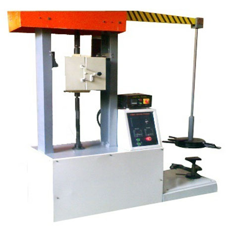
A typical (dead weight) creep frame (produced by Medilab Enterprises)
Variable Load Machines
It is, of course, possible to have a loading frame in which the force (usually produced either by screw-driven or hydraulic systems) can be varied during the test. A typical facility of this type is shown below. Such machines can readily generate forces of up to hundreds of kN. With the strain (extension) being continuously monitored, software control can be used to change the applied load such that a true stress is maintained. However, it is worth noting that such machines tend to be expensive. They’re not well-suited to very long term tests, both because of potential wear on the loading system and because tying up such expensive facilities for long periods is not economically attractive. If a number of samples are to be tested over periods of weeks or months, which is not unusual for creep testing, then it is much more likely that a set of dead weight machines will be used.
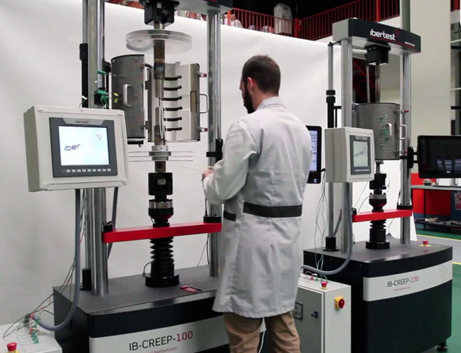
A typical (variable load) creep loading frame (produced by IBERTEST)