Materials for Nuclear Power Generation (all content)
Note: DoITPoMS Teaching and Learning Packages are intended to be used interactively at a computer! This print-friendly version of the TLP is provided for convenience, but does not display all the content of the TLP. For example, any video clips and answers to questions are missing. The formatting (page breaks, etc) of the printed version is unpredictable and highly dependent on your browser.
Contents
Main pages
Additional pages
Aims
On completion of this TLP you should be able to:
- understand the basic physics behind nuclear fission;
- describe the common features of nuclear reactors;
- understand the various neutron cross-sections;
- explain the mechanisms of radiation damage, and its consequences, particularly for structural steels;
- understand the material problems associated with extreme conditions, in particular large radiation fluxes;
- explain the materials selection for the components at the heart of a nuclear reactor:
- moderators;
- control rods;
- cladding.
Before you start
Readers should be familiar with the concept of a crystal lattice, dislocations, and diffusion. A familiarity with the basics of mechanical behaviour and corrosion of materials would also be useful.
Readers should be familiar with standard nuclear terminology: the definitions of isotope and nuclide, the composition of nuclei, the definitions of atomic number and mass number.
A note on units: throughout this TLP the unit used for energy is the electron volt , the energy associated with one electronic charge (1.619 × 10⁻¹⁹ C) subjected to a potential difference of 1 V, i.e. 1 eV ≈ 1.619 × 10⁻¹⁹ J
Introduction to Nuclear Processes
Each nucleus, consisting of protons and neutrons (collectively known as nucleons), has an associated binding energy. A graph of binding energy per nucleon is shown in the graph below. The total binding energy of a nucleus is the energy released when a nucleus is assembled from individual nucleons; the greater the energy release, the lower the potential energy of the nucleus, so higher binding energy in the graph represents greater stability. When one nucleus is converted to another or others of higher binding energy, whether that be through a natural radioactive process or through an artificially induced process, the difference in the total binding energies of the nuclei is released as kinetic energy of the particles produced and gamma rays. This energy can be harnessed through traditional methods, e.g. by heating water to generate steam to drive a turbine, and so electricity can be produced.
Origins of Binding Energy
The measured binding energies of the nuclides can be fitted reasonably well by Weizsäcker’s formula (see below). The formula is derived by treating the nucleus as analogous to a liquid drop, with surface energy and volume energy terms leading to the two dominant contributions: a term proportional to A, the atomic mass and to the volume of the nucleus, and a term proportional to -A2/3 due to the surface energy. These two terms compete, much in the same way they do in other processes (e.g. nucleation), facilitating a qualitative understanding of why nuclei split up or join together under certain conditions.
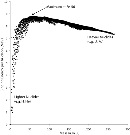
A graph of the binding energy per nucleon, in MeV, for common nuclides.
Fusion
Energy is given off when a nucleus becomes more stable, i.e. approaches the maximum on the graph above. Moving from lighter nuclei towards this maximum requires two nuclei to combine and form a heavier one (fusion), whereas moving from heavier nuclei towards this maximum requires the nucleus to split apart (fission). The energy release per mass of nuclide is much higher for fusion than for fission. Fusion has many other attractive attributes as a basis for power generation, but since nuclei are positively charged, sufficient energy most be put into the system to overcome the repulsion between nuclei so that a fusion process can occur. This Coulomb barrier can also be expressed as an ignition temperature. The technical challenges are many, and nothing close to a commercially viable reactor currently exists. Fusion for power generation is still a prominent research topic, and experimental reactors are in the process of being built, such as ITER (International Thermonuclear Experimental Reactor), which is planned to be completed by 2018.
Since nuclear fusion is not yet a practical power source, this TLP will instead focus on nuclear fission as means to generate heat and electricity.
Fission
Nuclear fission, as previously mentioned, involves splitting a heavier nucleus into two lighter nuclei. Fission can be induced if a nucleus absorbs a neutron of sufficient energy. If a nucleus undergoes fission regardless of the incident neutron energy, the nucleus is referred to as fissile; otherwise, if there is a threshold energy then the nucleus is referred to as fissionable.
Examples of fissile nuclides include 233U, 235U and 239Pu. The nuclide most commonly used in nuclear reactors is 235U.
A neutron will not necessarily induce fission if it passes through the nucleus. For example, fast neutrons are less likely to induce fission in 235U than thermal neutrons (i.e. neutrons with kinetic energy of the order of kT). Qualitatively, this makes sense since the faster a neutron is travelling the less time it spends inside the nucleus and so the less opportunity it has to induce fission within the nucleus. The actual reasons for this are complicated, and this topic is explored further on the “Cross Sections” page.
Fissionable nuclides, such as 238U and 239Pu, are also used in so-called “fast” reactors, where the neutrons are travelling fast enough (commonly around 10% the speed of light, or 1 MeV) to overcome the activation energy required to make fissionable nuclides decay.
The movie below illustrates the fission process:
Video illustrating nuclear fission
As can be seen in the movie, the parent nucleus decays into two fission fragments of unequal mass with a combined kinetic energy of about 169 MeV and several neutrons with a kinetic energy of about 2 MeV each (for 235U, the average number of neutrons produced is 2.4, but can be as high as 5). These neutrons are highly energetic, with 7–8 orders of magnitude more energy than thermalized neutrons. A gamma ray of about 7 MeV is also released. The neutrons could induce further fission events in other nuclei and thus cause a chain reaction, but in practice they are too fast and must first be slowed down inside the reactor.
![This graph shows that fragments formed tend to be of unequal masses, with each fragment being Gaussian distributed about a particular lower/higher mass respectively. Graph is under a CC[BY][NC][SA] license graph and was created from source data at http://www-nds.iaea.org/sgnucdat/c1.htm](images/fission-products-graph.png "This graph shows that fragments formed tend to be of unequal masses, with each fragment being Gaussian distributed about a particular lower/higher mass respectively. Graph is under a CC[BY][NC][SA] license graph and was created from source data at http://www-nds.iaea.org/sgnucdat/c1.htm")
Graph showing the distribution of fission fragment mass numbers for three nuclides, U-233, U-235 and Pu-239.
The fragments formed tend to be of unequal masses, with each fragment showing a Gaussian distribution about a particular lower or higher mass. [Graph is under a CC[BY][NC][SA] licence and was created from source data at http://www-nds.iaea.org/sgnucdat/c1.htm]
The nuclides produced by fission are usually of unequal mass, as shown in the graph above. The x-axis of the graph is by atomic mass, not atomic number. Many fission fragments are highly unstable, and decay by giving off beta radiation: this involves a neutron changing into a proton within the nucleus, leaving the overall number of nucleons (and hence the mass of the nucleus) the same.
Introduction to Nuclear Power Generation
There are two main types of nuclear reactor, characterized by the speed of the neutrons which induce fission:
- Thermal reactors. These are the predominant kind, using slower neutrons to induce fission, the basic fissile nuclide being U-235.
- Fast breeder reactors. In these less-common reactors, the fast neutrons are used directly to create (breed) fissile nuclides from fissionable nuclides; most commonly Pu-239 is bred from U-238. Pu-239 is also used in nuclear weapons.
There are many varieties of nuclear reactor, but all have the following common elements:
Fuel: The material that undergoes fission. This needn’t have the fissionable nuclides in the form of the element. The fuel is often in the form of a ceramic.
Cladding: This encases the nuclear fuel, isolating it mechanically and chemically from its immediate environment.
Moderator: Necessary in thermal reactors to slow down the neutrons produced by the fission process. Commonly, the moderator is in the form of a rod, but can be in liquid form or even be mixed with the fuel itself.
Control: This can be used to absorb excess neutrons, or even shut down the reactor in an emergency. Most often, the control material is in the form of a rod.
Core: The heart of the reactor, containing the fuel. The fuel is encased in cladding, and core must also accommodate the coolant and allow for more moderating rods or control rods to be added.
Coolant: The coolant removes heat from the reactor core into a heat exchanger. Note that the coolant itself is not cool, just that it removes heat from the core.
Reactor vessel: This contains the reactor core and the coolant. It often also acts as a reflector, reducing the loss of neutrons to the outside environment.
Generator/turbine: The heat generated by the reactor core generates steam, used to drive a turbine, which can generate electricity.
The following simulation demonstrates these main components in use.
The types of reactor are loosely grouped into generations describing the time period in which they were first used. Advances in technology have led to new designs.
The current generation of reactors can be defined by the materials used for each of these components. They include Pressurised Water Reactors (PWR), the most common reactor type, Boiling Water Reactors (BWR), CANDU or Pressurised Heavy Water Reactor (PHWR). These all include water as a coolant in some form. There are also Gas Cooled Reactors (GCR) and Advanced Gas Cooled Reactors (AGR), which use CO2 as coolant. Finally, there are also Liquid Metal Fast Breeder Reactors (LMFBR), which are cooled by a liquid metal (sodium or lead). There are also many other forms of reactors used for research purposes.
The next generation, commonly referred to as Generation IV, in some cases are just incremental improvements on these designs, but in other cases are radically different designs aimed at increasing efficiencies and reducing risk. The latter may demand materials which can sustain exposure to much more extreme environments.
Cross-Sections
To understand the rest of this TLP, it is vital to know about cross-sections.
What is a Cross-Section?
A cross-section quantifies the probability that a particle passing through a material will interact with the material. For example, a neutron absorption cross-section would quantify the probability that a neutron is absorbed as it travels through a material.
The following equation is a definition of the nuclear cross section σ
\[\sigma = \frac{C}{{N\delta .I}}\]
For neutrons passing through a plate of thickness δx (m), C is the number of events occurring per unit area (m−2), N is the number of nuclei per unit volume, or nuclear number density (m−3), and I is the number of neutrons passing through a unit area (m−2). As the behaviour depends on neutron energy, the cross-section must be specified for neutrons of a given energy (i.e. monoenergetic).
The Nδx term is often grouped together, since when multiplied by σ it is equal to C / I, a dimensionless quantity that is the probability of a neutron interacting, i.e. the ratio of the number of events occurring per unit area to the number of neutrons travelling through that same area.
Types of Cross-Section
Several different cross-sections will be mentioned in this TLP. Standard notation is used below, where (a,b) means an atomic interaction in which a is absorbed and b is emitted.
Elastic scattering (n,n): the cross-section of a neutron undergoing elastic scattering by a nucleus The total kinetic energy of the neutron and the nucleus is the conserved. Any energy that the neutron loses is due to the nucleus recoiling after the neutron is scattered.
Inelastic scattering (n,n'): a neutron is briefly absorbed by a nucleus, leaving it in an excited state. The nucleus can later return to its ground state, losing its excess energy as a gamma ray.
Radiative capture (n,γ): a neutron is absorbed by a nucleus, which gives out a gamma ray as a result.
Fission (n,f): neutron causes a nucleus to split into fragments and more neutrons.
Alpha decay (n,α): neutron causes a nucleus to lose two protons and two neutrons in the form of a helium nucleus. This interaction is important when considering the transmutation of elements, and how radioactivity is induced in a material.
Virtually any possible interaction has its own specific cross section; the ones above are just some of the most common. Other important interactions include (n,p) and (n,2n).
Cross-Section and Neutron Energy

Graph showing neutron cross-section against neutron energy. [Adapted from graph by Napy1Kenobi CC[BY][SA], source data unknown]
As the log-log graph above shows, cross-sections vary with neutron energy. Since most neutrons are in the thermal range (about 0.025 eV, or about 4 × 10⁻²¹ J), cross-sections are often quoted for this neutron energy.
Even though cross-sections do vary with energy, nuclides still have characteristically "high" or "low" cross sections. For example, as the graph shows, 235U (n,γ) has a higher cross section than 233U (n,γ) over almost all energy ranges.
The peaks in the graph are due to resonance effects. The reasons for these are beyond the scope of this TLP.
The Macroscopic Cross-Section
So far we have examined the microscopic cross-section. When talking about actual materials, the macroscopic cross-section is more commonly used.
Each element present in a material has its own macroscopic cross-section (m−1) defined by the following equation, where N is the nuclear number density as used earlier (m−3).
\[\Sigma_{i} = N_{i}\sigma_{i}\]
And for the material as a whole, its macroscopic cross-section is therefore:
\[\Sigma = N_{1}\sigma_{1} + N_{2}\sigma_{2} + \cdot \cdot \cdot + N_{i}\sigma_{i} + \cdot \cdot \cdot\]
The macroscopic cross-section is the probability that a neutron will undergo a reaction per unit path length travelled in the material.
The probability that a neutron travels a distance x without interacting therefore is:
$$\exp(-\Sigma x)$$
And the neutron mean free path, i.e. the average distance a neutron travels before interacting, can be found by integrating over this quantity as follows:
$$\lambda = \int_0^\infty x {\rm{P}}(x){\rm{d}}x = \int_0^\infty x \Sigma \exp ( - \Sigma x){\rm{d}}x = {1 \over \Sigma }$$
Interactive Graph of Macroscopic Cross Section
Try out the graph below to see what effect mass, density and microscopic cross-section have on the macroscopic cross-section. The nuclear number density is calculated by simply working out the number of nuclei present in the material given the molar mass and its density. This method makes the approximation that all the mass is present as nuclei, which is true to a reasonable degree of accuracy (electrons also have mass, but are only about 1/2000 the mass of a single nucleon and so do not contribute significantly).
The graph is editable: double-click on a cell to edit the numbers given. The arrows along the x-axis show the mean free path of the neutron through the material.
Mechanisms of Radiation Damage 1
Most of the radiation damage in a reactor is from the neutron flux being produced in the core. Other forms of radiation, such as gamma radiation, are very weakly interacting and don’t produce much effect. The principles in this section can in theory apply to any material, but the key materials are steels (e.g. a cold-worked 316 stainless steel).
Transmutation – (n, α) – Production of Helium
As seen in the previous section, there are several ways in which neutrons can interact with nuclei, including absorption of the neutron by the nucleus, making the nucleus unstable so that it decays, releasing an alpha particle in the process. Alpha particles consist of two protons and two neutrons, i.e. a 4He nucleus. Since they are 2+ positively charged, they are very highly ionizing, and will they quickly pick up electrons from the surrounding lattice and become elemental helium.
In stainless steels, the (n, α) interaction does not occur often with iron itself, but is mostly as a result of the nickel content of the alloy, as the graph of its cross section below shows.
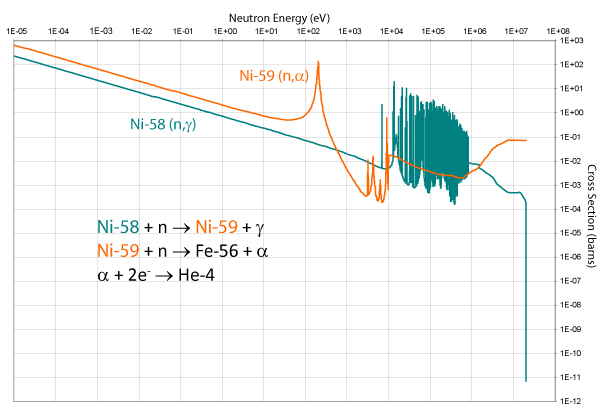
The presence of helium in the metal causes embrittlement and can act as a nucleation point for voids, which can lead to swelling.
Additionally, the neutron flux can induce further radiation. This occurs when a neutron transmutes an element into a radioactive one. This is undesirable, because it creates more low-level radioactive waste to contain when the reactor is eventually decommissioned.
Frenkel Defects
There are many proposed mechanisms of radiation damage, but on a fundamental level a single neutron scattering event can be considered.
If a neutron of sufficient energy scatters off a nucleus, the nucleus itself is displaced. The atom associated with the nucleus finds itself embedded into the structure elsewhere in a high-energy, interstitial site. It is termed a self-interstitial as the matrix and interstitial atoms are in principle the same. The site the atom previously occupied is now empty: it is a vacancy. In this way, self interstitial-vacancy pairs are formed, and these are called Frenkel defects.
Threshold Energy
At lower energies, the neutron collision causes the nucleus to vibrate, but the nucleus is not displaced. The excess energy is dissipated through the lattice as heat. The threshold energy to form a Frenkel defect depends on the nuclei present and the structure of the material (e.g. the phase of iron). It is typically in the range 10–50 eV (2–8 × 10⁻¹⁸ J). Note that when the neutron scatters off a nucleus, not all of its energy is transferred. This means that the minimum kinetic energy of the neutron is be larger than this threshold value, typically by a factor of 2–3.
This threshold energy is commonly given the symbol Ed. It is the energy required to overcome the potential barrier to move from one lattice site to another, and is approximately twice Es, the energy of sublimation, since twice as many bonds are broken to move an atom within a lattice as removing it from its surface, plus a contribution of 4–5 Ec, where Ecis the energy loss by electron stopping (required to allow the lattice to relax after the atom has been displaced).
Displacement Spikes
Neutron scattering events are not isolated. On average, each displaced atom might then go on to displace further atoms, and likewise the neutron that caused the first displacement might go on to displace further atoms. This means that there is a local cascade of displacements, known as a displacement spike, within which there is a large amount of disorder in the structure. This is illustrated with a simulation, below:
The Kinchin and Pease Model
A neutron scattering from an atom imparts an energy Ep to it. This primary knock-on atom (PKA) with energy Ep then displaces other atoms, ultimately giving a displacement cascade if Ep is high enough. The number of atoms displaced by the PKA is difficult to calculate, but a simple model (attributed to Kinchin and Pease) can capture much of the basic physics. The assumptions are:
- the cascade is a sequence of two-body elastic hard-sphere collisions;
- a minimum energy transfer Ed is required for displacement;
- the maximum neutron energy available for transfer is the cut-off energy Ec, set by loss to the electrons (electron stopping);
- the atoms are randomly distributed, so that channelling and other effects of crystal structure are ignored.
A full derivation can be found in Fundamentals of Radiation Science by Gary Was. The average number of atoms displaced by a PKA of energy Ep is:
0 for Ep< Ed
1 forEd < Ep< 2Ed
Ep/2Ed for 2Ed < Ep<Ec
Ec/2Ed for Ep ≥Ec
Mechanisms of Radiation Damage 2
Formation of Dislocation Loops
Both the interstitial atoms and vacancies can diffuse through the lattice, but the interstitial atoms are more mobile. Both interstitials and vacancies are eventually removed from the lattice (when they reach sinks such as dislocations or grain boundaries). However, they are also always being generated by the neutron radiation. Thus steady-state populations of interstitials and vacancies are formed.
There is a tendency for interstitial atoms and vacancies respectively to aggregate together into discs. This is again illustrated through an animation, below:
When there is a sufficient supersaturation of vacancies, the disc of vacancies grows and the gap between the planes on either side collapses to form a continuous lattice with a dislocation loop. Since the Burgers vector is normal to the plane loop, it is an edge dislocation and grows/shrinks by climb and moves by glide along a prism; it is termed a prismatic loop.
Nucleation and Growth of Voids
Vacancy dislocation loops should reduce the volume of the material whilst interstitial dislocation loops should increase it, as seen in the animation above. And, in general, we expect compensating vacancy and interstitial effects to leave the material with approximately the same volume. However, irradiated materials are in fact observed to swell.
To explain this, we consider what happens when vacancy loops join together. In practice, when the loops join they form three dimensional cavities a few nm in diameter. These voids contribute no net change in volume to the material, and so this just leaves the interstitial loops, which do lead to swelling in the material.
In the absence of any driving force, it would seem unlikely that enough voids would form for any appreciable effect to be observed on the material. This is where the transmutation of nickel becomes important, since the helium atoms produced are very small and are thus extremely mobile as interstitial atoms in the lattice. They quickly form bubbles, and these helium bubbles can act as nucleation points for void formation.
Effects of Radiation Damage
The previously discussed changes in microstructure due to radiation damage affect the macroscopic, mechanical properties of the material. These effects happen for a variety of reasons, but are generally less noticeable at higher temperatures as the damage caused by radiation is constantly being annealed out: at higher temperatures vacancy and interstitial mobility are increased so they are removed from the lattice faster.
The following table gives an overview of the effects observed.
| Material Property | Effect of Radiation Damage |
| Yield strength | Increases on irradiation, along with a decrease in plastic flow range. |
| Ultimate tensile strength | This also increases on irradiation, but less than the yield strength. |
| Ductile-brittle transition temperature | This marks the transition between a material exhibiting ductile behaviour at higher temperatures and brittle behaviour at lower temperatures. It increases significantly on irradiation, which can present a problem when the reactor vessel cools on shut down when internal pressure within the reactor is still high, and so fracture can occur if this is not taken into account. |
| Young’s modulus | Small increase on irradiation. |
| Hardness | Increase. |
| High-temperature creep rate | Increase during irradiation. |
| Ductility | Decrease. |
| Stress-rupture strength | Decrease. |
| Density | Decrease as the material swells on irradiation. |
| Impact strength | Decrease. |
| Thermal conductivity | Decrease on irradiation since lattice disorder increases, thus increasing phonon scattering. |
| Electrical conductivity | Decrease for similar reasons to thermal conductivity. |
The following sketch shows the stress-strain curve for a typical steel and its different form after irradiation.
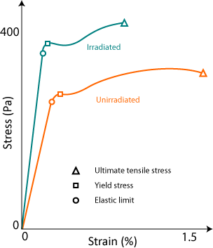 |
| A stress-strain curve for a stainless steel irradiated or not. |
Fuel and Cladding
Choice of Fuel
There are several important factors when choosing a nuclear fuel:
- The fuel itself must be easily fissionable, preferably fissile.
- The fuel must release sufficient quantities of neutrons per neutron captured to be able to sustain a fission chain reaction. Too many neutrons produced and a runaway, supercritical, reaction would occur which would be disastrous in the case of a nuclear reactor. The ratio of neutrons produced to neutrons absorbed can, however, be adjusted through use of control rods and moderators.
- The fuel must have a sufficiently long half-life. Fissile materials, by their very nature due to their instability, are radioactive. Radioactive materials decay exponentially, and this decay is quantified by their half-life, the time it takes for half of the radioactive nuclei present to decay into a more stable form. Nuclear fuels must therefore have a sufficiently long half-life, otherwise the nuclei would decay into a useless form before fission could be induced in a controlled manner.
- Economic factors are also important. The fuels must be abundant and readily available. Uranium is the only naturally abundant fissile material and exists in an ore, called uraninite (also known as pitchblende), which is primarily uranium (IV) oxide, mined primarily in Canada, Australia and Kazakhstan. It has an isotopic composition of 99.3% of the fissionable but not fissile 238U and just 0.7% of the fissile 235U. This means that it must first be enriched, a difficult and expensive process which raises the proportion of 235U to 238U.
- No plutonium occurs naturally, except in trace amounts as a result of the natural decay of uranium. It is instead made as a by-product in nuclear reactors, and must first be extracted from use nuclear fuels before it can be used.
- Political concerns are important; heavily enriched uranium and plutonium can be used for atomic weaponry and so are not favoured. This is why there is current interested in the thorium cycle, which produces 233U. Though this can in theory be used in atomic weaponry, it is always contaminated with 232 U, which is highly dangerous because of the amount of gamma radiation it emits and making it very difficult to handle. Before the 233U could be used as a weapon, the 232U would have to be removed, which is again very difficult. This inherent proliferation resistance, and thorium’s natural abundance (3–4 x as abundant as uranium), has increased interest in it in recent years.
- The common fission fragments formed are also important, both in the short-term due to the effects they have on structural materials in the reactor and also in the long-term since some fragments have very long half-lives and so will present problems as nuclear waste since it will need to be stored for much longer periods of time. It should be noted, however, that the longer the half-life of the fission product the less dangerous it is to people. This is a somewhat counter-intuitive point that is often missed, since a longer half-life means that less of the material decays and hence gives off dangerous radiation in a given period.
Form of Fuel
Metallic uranium is not favoured as a fuel since it is dimensionally unstable under irradiation, flammable, can readily corrode in oxygen-containing atmospheres, and can produce uranium dust which has a low-temperature flash-point and which can cause serious health problems if inhaled. There is some interest in using metallic U alloys as fuel when a particularly high density of fissile or fissionable nuclides is required.
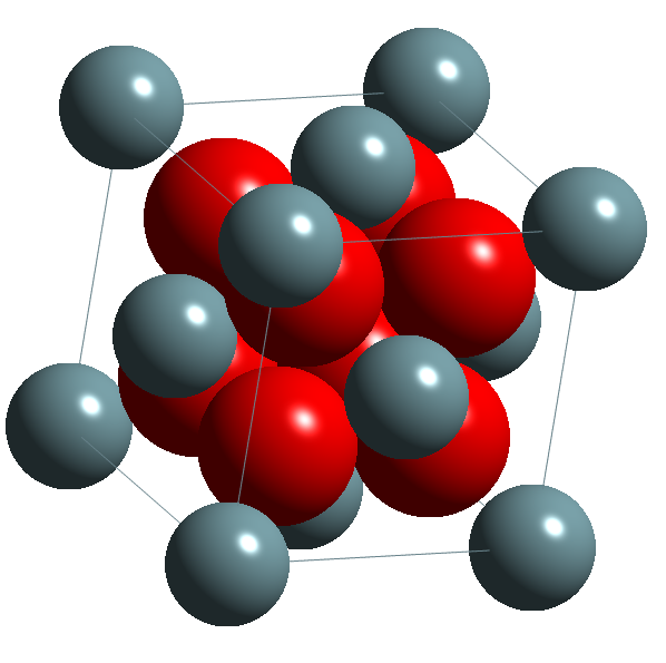
As an alternative, ceramic forms can be used, including UO2, U3O8, UC, U2C3, UN, U3Si and USi. The most common of these is uranium dioxide, which has the calcium fluorite structure shown in the image below.
Choice of Cladding
The nuclear fuel cannot be allowed to make direct contact with the coolant inside the reactor vessel, due to the potential for radioactivity to be released into the environment. Instead, cladding has to be used to surround the fuel.
Key design criteria are that the cladding should:
- be transparent to neutrons, so that it doesn’t absorb neutrons that could be used to induce further fission.
- have a high thermal conductivity, and not have a high thermal expansion coefficient.
Key problems include:
- hydrogen embrittlement due to (n, p) reactions inside cladding.
- swelling due to release of fission product gases.
Common choices for cladding material are stainless steel (in FBRs) Zircaloy (in PWRs) and, in the past, Magnox.
Moderators
A moderator is designed to slow down fast neutrons such that they are more easily absorbed by fissile nuclei. There are two main factors in choosing a moderator:
- The moderator must not absorb neutrons itself. This means it should have a relatively low neutron absorption cross-section.
- The moderator should efficiently slow down the neutrons. Modelling neutron-nuclei collisions as a classical elastic collision, in much the same way as gas molecules are modelled, gives the result that the closer the nucleus’ mass is to that of the neutron, the more energy will be transferred in the collision. This means that lighter elements are favoured.
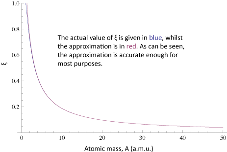
The following equation shows the fractional energy lost per collision, ξ, on average for a neutron colliding with a nuclide of mass A. E0 is the initial energy of the neutron, and Es is the energy after scattering has occurred.
$$\xi = \left \langle \ln \left( \frac{E_{0}}{E_{s}} \right) \right \rangle = 1 - \frac{(A-1)^{2}} {2A} \ln \left( \frac{A+1}{A-1} \right)$$
It is beyond the scope of this TLP to derive this equation, but the basic physics is straightforward. In elastic collisions kinetic energy and momentum are conserved and the energy lost by the neutron can be calculated for any given angle of contact. In three dimensions it is necessary to integrate over all possible angles to obtain an average.
The equation is well approximated by:$$\xi \approx \frac{6}{3A+2}$$
This is good enough for most purposes (to see the error in the approximation click here.). Since this is a classical derivation applied to a quantum situation, there is probably more error due to the original assumptions than this mathematical approximation.
Try out the interactive movie below to see this effect in action. The movie obeys the same physics used to derive the above equations, except in a two-dimensional rather than three-dimensional case. The simulation is meant to show energy lost per collision, and does not give an accurate impression of how often these collisions occur: interatomic distances have been greatly reduced for illustrative purposes. In practice it is the scattering cross-section which determines the rate of neutron collisions.
Finally, the above analysis can be modified with respect to the neutron cross-sections, by considering the ratio ξ (Σs / Σa). This weights ξ with the absorption and scattering cross-sections. The higher this ratio, the more appropriate the material is as a moderator.
Graphite
Historically, graphite has been a very popular neutron moderator, and is used in the majority of British reactors. However, the graphite used has to be highly pure to be effective. Graphite can be manufactured artificially using boron electrodes, and even a small amount of contamination from these electrodes can make the graphite unsuitable as a moderator since boron is a highly effective neutron absorber, and so it “poisons” the graphite by increasing the overall absorption cross section, Σa. It also has unique problems: it stores energy in metastable local defects when it is irradiated, particularly at lower temperatures. This so-called Wigner energy can be released suddenly when the graphite spontaneously returns to its stable phase, and this sudden rise in temperature is not desirable since it can cause further structural damage within the reactor. This means that graphite has to be annealed to remove the excess energy in its lattice in a controlled manner. The following movie shows three-dimensional models of the graphite lattice and demonstrates the origins of this metastable phase within the graphite lattice.
Other common choices:
Light Water
Hydrogen is a good candidate for a neutron moderator because its mass is almost identical to that of the incident neutron, and so a single collision will reduce the speed of the neutron substantially. However, hydrogen also has a relatively high neutron absorption cross-section due to its tendency to form deuterium, and so light water is only suitable for enriched fuels which allow for a higher proportion of fast neutrons.
Heavy Water
Heavy water has similar benefits to light water, but because its water molecules already have deuterium atoms it has a low absorption cross section. Additionally, because of the high energy of the fast neutrons, an additional neutron might be knocked out of the deuterium atom when a collision occurs, thus increasing the number of neutrons present. The main disadvantage of heavy water as a moderator is its high price.
Beryllium
Beryllium-9 is favoured, because in addition to being a light element, on collision with a fast neutron, it can react as follows:
9Be + n → 8Be + 2n
The main problems with beryllium are its brittleness as a metallic phase and its toxicity, which make it less favoured as a moderator than the other materials mentioned here.
Lithium Fluoride
Lithium fluoride is commonly used in molten salt reactors. It is mixed with the molten metal and the fuel, and so its structural properties as a solid are not important.
Summary
In this TLP, the process of nuclear fission has been described, thus explaining the common choices for nuclear fuel used commercially. Materials selection for the major components of a nuclear reactor have also been explored, including:
- Moderators, and how they work best when they consist of light nuclides with relatively low absorption cross-sections.
- Control rods, which require high absorption cross-sections, and how the same nuclides found in control rods, e.g. boron, can act as poisons significantly reducing the efficiency of a reactor if found elsewhere, such as in moderators.
- Cladding, which experiences much stronger radiation fluxes and extremes of temperature than any other structural material in the reactor, and so must be able to withstand these conditions.
Concepts such as neutron cross-section and neutron flux have been explained, and this allowed mechanisms of radiation damage inside structural steels, and the consequences of this, to be discussed.
Radiation materials science is a mature field, but there any many challenges for materials to permit more efficient operation, improve safety and reliability and reduce costs. As this TLP has shown, the basic mechanisms of damage caused by low levels of radiation are now well understood, but the much higher levels of radiation such as those that will be experienced in the new experimental fusion reactor, ITER, have yet to be satisfactorily contained. This TLP has given only an introduction to some of the important phenomena. To learn more, consult the Going Further section.
Test your understanding of this TLP by answering some of the questions in the next section.
Questions
The cross-section data needed to answer these questions have been supplied here. To find further cross-sections, consult the Evaluated Nuclear Data File (ENDF).
Quick questions
You should be able to answer these questions without too much difficulty after studying this TLP. If not, then you should go through it again!
-
Check which elements are fissionable but not fissile:
-
Which of the following are NOT suitable moderating materials?
-
Which of the following would NOT be classified as "Sabsorption" cross-sections?
-
Which of the following discourages void formation?
-
Which of the following material properties have lower values after irradiation?
Deeper questions
The following questions require some thought and reaching the answer may require you to think beyond the contents of this TLP.
-
Zirconium minerals are often found with small amounts of hafnium present due to their chemically similar nature. Zirconium is also used as a primary component of Zircaloy, a cladding material designed to be almost transparent to neutrons.
By comparing how the mean free path of a thermal neutron in pure zirconium differs from that of zirconium with 0.01% hafnium impurities, comment on the consequences of hafnium impurities in Zircaloy.
(Zr: A = 91.22, ρ = 6.52 g cm−1, σc = 0.18 barns;
Hf: A = 178.49, ρ = 13.31 g cm−1, σc = 105 barns)
Going further
Books
- Was, G. A., Fundamentals of Radiation Materials Science, Springer, 2007. (and see the movies at http://www.sitemaker.umich.edu/was)
- Ma, B. M., Nuclear Reactor Materials and Applications, Van Nostrand, 1983.
- Glasstone, S. and Sesonske, A., Nuclear Reactor Engineering, Third Edition, Van Nostrand, 1981
Websites
- Evaluated Nuclear Data File: [ http://www.nndc.bnl.gov/sigma/]
- Nuclear Data Services: [ http://www-nds.iaea.or.at/]
Papers and other publications
- MRS Bulletin, various articles feature topics relating to Nuclear power including Volume 34, January 2009.
- On void formation: L.K. Mansur, Theory and experimental background on dimensional changes in irradiated alloys, Journal of Nuclear Materials, Volume 216, October 1994, Pages 97-123, DOI: 10.1016/0022-3115(94)90009-4.
- On Wigner energy: R.H. Telling, et al., Wigner defects bridge the graphite gap, Nature Materials, Volume 2, April 2003, Pages 333-337, DOI: 10.1038/nmat876.
Approximated Equation
Academic consultant: Lindsay Greer (University of Cambridge)
Content development: Matthew Horton
Photography and video: Brian Barber
Web development: Lianne Sallows and David Brook
This DoITPoMS TLP was funded by the UK Centre for Materials Education and the Department of Materials Science and Metallurgy, University of Cambridge.