Crystallography (all content)
Note: DoITPoMS Teaching and Learning Packages are intended to be used interactively at a computer! This print-friendly version of the TLP is provided for convenience, but does not display all the content of the TLP. For example, any video clips and answers to questions are missing. The formatting (page breaks, etc) of the printed version is unpredictable and highly dependent on your browser.
Contents
Aims
On completion of this TLP you should:
- Have an understanding of the basic concepts of crystallography, i.e. lattices, motifs, symmetry elements etc.
- Be able to identify lattices and symmetry elements within those lattices.
- Know about the different types of unit cell.
- Understand the idea of close-packing and packing efficiency.
- Be familiar with the different crystal systems and Bravais lattices.
Before you start
There are no special prerequisites for this TLP.
Introduction
Crystalline materials are characterised by a regular atomic structure that repeats itself in all three dimensions. In other words the structure displays translational symmetry. Translational symmetry is illustrated in this image of the crystal structure of the mineral cordierite (Mg2Al4Si5O18) taken with a high resolution transmission electron microscope. The image is a projection through a very thin slice (~200 Å thick) of the atomic distribution. Black spots correspond to hollow channels through the structure and white spots correspond to regions of high electronic density, arranged around the channels in 6-fold rings (Scale: the distance between the black spots is ~ 9.7 Å). The structure consists of a simple group of atoms that repeats itself periodically in space. This periodicity can be revealed using the concept of a lattice.
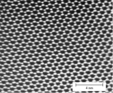
A. Putnis, Introduction to Mineral Sciences, Cambridge University Press, 1992 - frontispiece
Lattices
Crystalline structures are characterised by a repeating pattern in three dimensions. The periodic nature of the structure can be represented using a lattice.
To generate the lattice from any repeating pattern, we choose an arbitrary reference point and examine its environment. We then simply mark in all the points in the pattern that are identical to the chosen reference point. The set of identical points is the lattice, and each point within it is a lattice point.
A. Putnis, Introduction to Mineral Sciences, Cambridge University Press, 1992
Note that not all white discs within this pattern are exactly equivalent, and therefore they are not all lattice points. The discs marked with a black spot have different arrangements around them than those that are unmarked (each is surrounded by 3 others in a triangle, but the orientation of the triangles is different).
To practice identifying the lattice points within a more complex repeating pattern, try the following game! The brick pattern corresponds to an unusual style of Danish bricklaying where after each normal brick, the next is laid breadthwise,and so on. The original image was taken from the wall of the Centre for Electron Nanoscopy in Copenhagen (thanks to Dr Rafal Dunin-Borkowski).
Unit Cell
The structure of a crystal can be seen to be composed of a repeated element in three dimensions. This repeated element is known as the unit cell. It is the building block of the crystal structure. We define the unit cell in terms of the lattice (set of identical points). In three dimensions the unit cell is any parallelepiped whose vertices are lattice points, in two dimensions it is any parallelogram whose vertices are lattice points.
Of course this definition means that there are an infinite number of possible unit cells. So, in general, the unit cell is chosen such that it is the smallest unit cell that reflects the symmetry of the structure. There are two distinct types of unit cell: primitive and non-primitive. Primitive unit cells contain only one lattice point, which is made up from the lattice points at each of the corners. Non-primitive unit cells contain additional lattice points, either on a face of the unit cell or within the unit cell, and so have more than one lattice point per unit cell.
It is often the case that a primitive unit cell will not reflect the symmetry of the crystal structure. A suitable non-primitive unit cell will be picked in such cases.
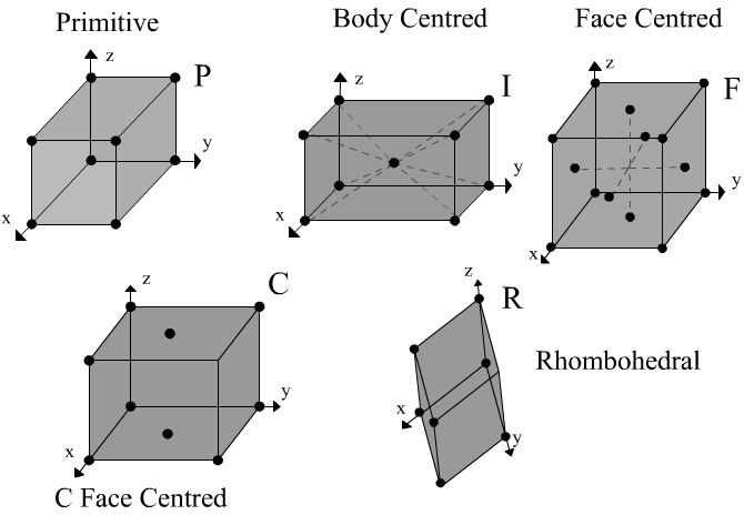
It was mentioned above that the (eight) lattice points at the corners of the unit cell contribute only one lattice point to the cell. This is because the lattice points at the corners are shared between eight unit cells. Each corner lattice point therefore is equivalent to 1/8 of a lattice point per unit cell. Similarly lattice points on the edge of a unit cell are shared among four unit cells and are worth 1/4 of a lattice point per unit cell. Lattice points on the face of a unit cell are shared between two unit cells and are worth 1/2 of a lattice point per unit cell. Lattice points contained entirely within the unit cell are worth one lattice point per unit cell.
The most common types of unit cell are the primitive(P) unit cell with one lattice point per unit cell; the face centred(F) unit cell with additional lattice points at the centre of each face and four lattice points per unit cell; and the body centred(I) unit cell with a lattice point in the middle of the unit cell and two lattice points per unit cell. Other cell types are the C face centred unit cell and the rhombohedral unit cell.
Lattice geometry
To define the geometry of the unit cell in 3 dimensions we choose a right-handed set of crystallographic axes, x, y, and z, which point along the edges of the unit cell. The origin of our coordinate system is at one of the lattice points.
Lattice parameters
The length of the unit cell along the x, y, and z direction are defined as a, b, and c. Alternatively, we can think of the sides of the unit cell in terms of vectors a, b, and c. The angles between the crystallographic axes are defined by:
α = the angle between b and c
β = the angle between a and c
γ = the angle between a and b
a, b, c, α, β, γ are collectively known as the lattice parameters (often also called ‘unit cell parameters’, or just ‘cell parameters’).
Lattice vectors
A lattice vector is a vector joining any two lattice points. Any lattice vector can be written as a linear combination of the unit cell vectors a, b, and c:
t = U a + V b + W c
In shorthand, lattice vectors are written in the form:
t = [UVW]
Negative values are not prefixed with a minus sign. Instead a bar is placed above the number to denote that the value is negative:
t = −U a + V b − W c
This lattice vector would be written in the form:
t = [V]
Lattice directions are written the same way as lattice vectors, in the form [UVW]. The direction in which the lattice vector is pointing is the lattice direction. The difference between lattice directions and lattice vectors is that a lattice vector has a magnitude which can be shown by prefixing the lattice vector with a constant. By convention U, V and W are integers.
Many crystal systems have elements of symmetry. In these systems, certain sets of directions are symmetrically equivalent to each other. The set of directions that are symmetrically related to the direction [UVW] are written <UVW>.
Crystal structure
The structure of a crystal can be described by combining the following elements: the lattice type, the lattice parameters, and the motif.
The lattice type defines the location of the lattice points within the unit cell.
The lattice parameters define the size and shape of the unit cell.
The motif is a list of the atoms associated with each lattice point, along with their fractional coordinates relative to the lattice point. Since each lattice point is, by definition, identical, if we add the motif to each lattice point, we will generate the entire structure:
Plan view
Knowing the motif and lattice it is possible to construct a Plan view of the crystal structure. The Plan view is the standard representation of a crystal structure and is very easy to produce. It is generally the 2D projection looking down the [001]/z-axis of the unit cell. Note this is equivalent to constructing a projection on the (001) plane. Refer to Lattice Planes and Miller Indices TLP for information on lattice planes.
The Plan view generally displays a 2×2 array of unit cells. The heights of the atoms within the unit cell are represented by fractions next to them, the fraction indicating that atom's fractional height in terms of the unit cell height (c) (atoms at the top and bottom of the unit cell have no numbers next to them). On constructing the plan view it is essential to not only indicate heights of atoms within the unit cell but also define the crystallographic axes you are using along with tracing out the unit cell.
Close packing and packing efficiency
In many cases the atoms of a crystal pack together as tightly as possible. Approximating atoms as hard spheres they will achieve this by forming a close-packed structure. This is the case for most metallic structures.
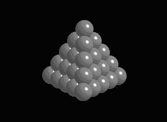
The main ideas of close packing are demonstrated in the animation below
In a close-packed structure the close packed directions are the directions in which atoms are touching. For a hcp structure the close packed directions are [100], [010] and [110] and their negatives. Directions that are related by symmetry are represented using the notation <UVW>. The close packed directions for hcp are then <100>.
The close packed directions for ccp, which has a fcc unit cell, are along the diagonals of each face, [110], [101], [011]… etc. The set of directions that are related to these by symmetry are the <110> set.
Packing Efficiency
The packing efficiency of a crystal structure tells us how much of the available space is being occupied by atoms. It is usually represented by a percentage or volume fraction.
The packing efficiency is given by the following equation:
$${{\left( {number\,of\,atoms\;per\;cell} \right)*\left( {volume\;of\,one\,atom} \right)} \over {volume\;of\;unit\;cell}}\,$$
The steps usually taken are:
- Calculate the volume of the unit cell
- Count how many atoms there are per unit cell
- Calculate the volume of a single atom and multiply by the number of atoms in the unit cell
- Divide this result by the volume of the unit cell
The steps are straightforward. The main source of difficulty is expressing the volume of the unit cell in terms of the radii of the atoms (or vice versa). Knowing the close-packed directions makes this step easier for us. The animation below demonstrates how to calculate the packing efficiency of hcp, ccp and bcc structures.
Note: If you know the motif, an easy way to find the number of atoms per unit cell is to multiply the number of atoms in the motif by the number of lattice points in the unit cell.
Symmetry
We have already met the concept symmetry in relation to crystal structures: the lattice generates the translational symmetry—the motif is repeated on every lattice point.
Other types of symmetry exist, including:
- rotation axes
- mirror planes
- centre of symmetry
- inversion axes (combination of rotation and centre of symmetry operations)
An n fold rotational symmetry operation rotates an object by 360°/n. Only n = 1, 2, 3, 4, and 6 are permitted in a periodic lattice
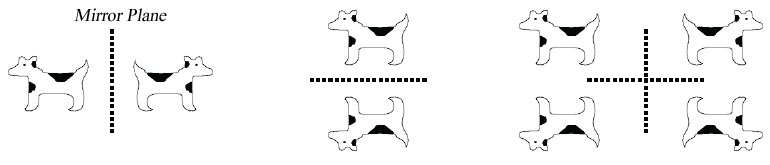
An object has mirror symmetry if reflection of the object in a plane brings it into coincidence with itself:
Some objects have special symmetry about an origin such that, for any point at position x, y, z, there is an exactly similar point at –x, –y, –z. The origin is called a centre of symmetry ( “inversion centre”). Such an object is said to be centrosymmetric:
An n-fold inversion axis is a combination of a rotation by 360/n followed by a centre of symmetry operation. An example of a 4-fold inversion axis is show in the following animation:
Combining symmetry
Only certain combinations of symmetry operation can exist in a crystal structure. This is because one symmetry element operating on another will generate a third symmetry element in the structure and this can end up generating an infinite number of symmetry elements, as shown in the animation below:
In fact, there are only 32 permitted combinations of mirror planes, rotation axes, centres of symmetry and inversion axes. These are known as the 32 point groups. Each point group is a finite set of mutually compatible symmetry elements. When the symmetry elements of a point group are operated on each other, they simply generate one of the other elements within the group.
Crystal systems
The rotational symmetry of a crystal places constraints on the shape of the conventional unit cell we choose to describe the structure. On this basis we divide all structures into one of 7 crystal systems. For example, for crystals with 4 fold symmetry it will always be possible to choose a unit cell that has a square base with a = b and γ = 90°:
There are 14 unique combinations of the 7 crystal systems with the possible types of primitive and non-primitive lattices. These are referred to as the 14 Bravais lattices.
Crystal systems, lattices and symmetry elements
Crystal System |
Defining Symmetry |
Unit Cell Geometry |
|
Triclinic |
Translational Only |
a≠b≠c; α≠β≠γ |
|
Monoclinic |
A diad axis |
a≠b≠c; α=γ=90°; β>90° |
|
Orthorhombic |
3 diads |
a≠b≠c; α=β=γ=90° |
|
Trigonal For more information click here |
1 triad |
a=b≠c; α=β=90°; |
|
Hexagonal |
1 hexad (parallel to [001]) |
a=b≠c; α=β=90°; |
|
Tetragonal |
One tetrad |
a=b≠c; α=β=γ=90° |
|
Cubic |
4 triads |
a=b=c; α=β=γ=90° |
|
Bravais Lattice Structures
|
|
|
|
|
|
|
|
|
|
|
|
|
|
|
|
|
|
|
|
Summary
This TLP has covered the following topics:
- The mathematical description of the atomic structure of a crystal.
- The different lattice types.
- What a lattice vector, unit cell & motif are and how they are relevant to describing crystals.
- Close packing and the packing efficiency of a crystal structure.
- What symmetry operators are present within a crystallographic lattice and how only specific combinations of such symmetry elements may exist.
- Bravais lattice and Point Groups.
- How to construct the plan view of a 2×2 unit cell.
Questions
Quick questions
You should be able to answer these questions without too much difficulty after studying this TLP. If not, then you should go through it again!
-
Which of these is not a lattice type ?
-
What is a lattice ?
-
How many Bravais lattices (3D) are there ?
-
How many point groups (3D) are there ?
-
What is a unit cell ?
Deeper questions
The following questions require some thought and reaching the answer may require you to think beyond the contents of this TLP.
-
Construct a plan view of NaCl (sodium chloride).
NaCl has a face-centred cubic lattice. The motif is:
Cl @ (0,0,0);
Na @ (0,0,1/2);
Note 1: The motif coordinates are positions relative to each lattice point
Note 2: In a face centred cubic structure the lattice points are located at:
(0,0,0), (1/2,1/2,0), (1/2,0,1/2), (0,1/2,1/2) -
Diamond has a face centred cubic lattice. Its motif is
C @ (0,0,0), (1/4,1/4,1/4)
Construct a plan view of the diamond unit cell.
Treating the carbon atoms as hard spheres calculate the packing efficiency of diamond.
Note: In a face centred cubic structure the lattice points are located at:
(0,0,0), (1/2,1/2,0), (1/2,0,1/2), (0,1/2,1/2)
Going further
Books
- A. Putnis, Introduction to Mineral Sciences, Cambridge University Press, 1992
- Feynman, Leighton, Sands, Lectures on Physics Vol. II, Chapter 30, Addison-Wesley Publishing Company, 1964 [Note: This book follows a different convention when referring to body-centred and face-centred structures]
- C. Hammond, The Basics of Crystallography and Crystallography, III Ed, Oxford University Press, 2009
- B.D Cullity, S.R Stock, Elements of X-Ray Diffraction, Prentice Hall, 2001
- McKie, McKie, Essentials of Crystallography, Blackwell Scientific Publications, 1986
Website of International Tables for Crystallography http://it.iucr.org/A/
Academic consultant: Richard Harrison, Zoe Barber (University of Cambridge)
Content development: James Hickey, Andrew Gibbons
Web development: Lianne Sallows and David Brook
This DoITPoMS TLP was funded by the UK Centre for Materials Education and the Department of Materials Science and Metallurgy, University of Cambridge.