Experiment: Measurement of Young's modulus
View a definition of Young's Modulus.
A cantilever beam is fixed at one end and free to move vertically at the other, as shown in the diagram below.
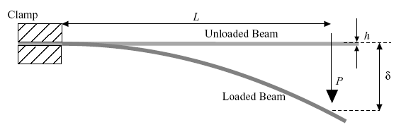
Geometry of the cantilever beam test.
For each of three strips of material (steel, aluminium and polycarbonate), the strip is clamped at one end so that it extends horizontally, with the plane of the strip parallel to the plane of the bench. A small weight is hung on the free end and the vertical displacement, δ, measured. The value of δ is related to the applied load, P, and the Young’s Modulus, E, by
|
\[\delta = \frac{1}{3}\frac{{P{L^3}}}{{EI}}\] |
(1)
|
where L is the length of the strip, and I the second moment of area (moment of inertia). View derivation of equation.
For a prismatic beam with a rectangular section (depth h and width w), the value of I is given by
|
\[I = \frac{{w {h^3}}}{{12}}\] |
(2)
|
By hanging several different weights on the ends of the strips, and measuring the corresponding deflections, a graph can be can be plotted which allows the Young's modulus to be calculated. This is repeated for each of the three materials. The calculated values for the Young’s modulus may be compared with the values in this properties table.
Experiment to determine Young's modulus