Typical steps during FEM modelling
Consider a wall mounted bracket loaded uniformly along its length as in the figure below:
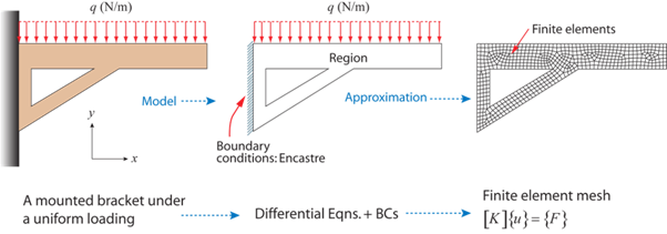
Wall mounted bracket
The geometry (field) is defined for us and is (relatively) complex. The boundary conditions are also defined and are:
- A uniform force per unit length (Neumann condition) along the upper edge
- Fixed x and y displacements along the clamped edge (Dirichlet condition)
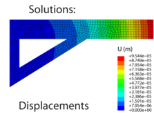
It is apparent that the bracket will respond mechanically under the action of the applied load and a system of internal stresses will develop (to balance the applied load). To calculate the stresses that develop we must first mesh (discretise) the domain, assemble the global stiffness matrix [K], and then determine the nodal displacements {u} and resultant forces {F} using some iterative numerical technique (Gauss elimination, for instance). It is then a relatively trivial exercise to compute the nodal stresses from the nodal displacements and to find the solution between the nodes and within the elements using shape functions.
 \(\underrightarrow {{\sigma _{ij}} = {C_{ijkl}}{\varepsilon _{kl}}}\)
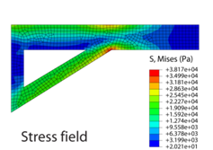
However, it is important to be aware that certain combinations of the specified number of elements (mesh density) and the specified element order can give rise to solutions that are highly inaccurate. It is highly advisable (and good practice) to perform a mesh sensitivity study, whereby the effect on the solution of successively finer meshes is analysed in order to eliminate any mesh sensitivity. The following application demonstrates this point:
The application below concerns the deflection of a CANTILEVER beam loaded at its end with an applied force. The width of the beam can be altered, although the beam length and beam depth are fixed constant. The beam can be made of either steel or aluminium and it can be loaded with a force of either 40 N or 80 N. The beam can then be meshed with either 2 elements through its thickness or 4 elements through its thickness. The elements can be either first or second order. For any combination chosen, a prediction of the beam deflection based on finite element calculations will be compared to predictions from (analytical) ordinary beam bending equations. It should become apparent that the error between the two decreases as the mesh density and element order are increased.