Toughness in compression
Up to this point in the TLP, we have mainly considered toughness behaviour in tension, such as in the failure of brittle materials like ceramics and the toughening of fibrous materials in tension through fibre pull out. Here, we consider the toughness of metals, ceramics and fibre-reinforced composites in compression.
Metals
In metals, compressive stresses initially cause fully elastic behaviour. As with tensile stresses, the onset of plasticity under compression causes dislocation glide. In f.c.c. metals and b.c.c. metals where five independent slip systems are able to operate to produce a general plastic shape change of a polycrystalline material, the very toughening mechanisms responsible for toughness in tension are the same as those responsible for toughness in compression.
For h.c.p. metals such as titanium and zirconium, for which five independent slip systems do not operate at room temperature, general plastic shape changes are able to occur by a combination of slip and deformation twinning, both in tension and compression. In Figure 11 below, a cylinder of commercial purity (CP) titanium subjected to a very high compressive force and a very high rate of strain by being fired at 250 m s−1 is shown impacting a hardened steel target. The CP titanium cylinders were encased in nylon sabots used to provide a low friction seal with the gas gun used for these experiments. Note how the cylinder has deformed after this experiment, producing a characteristic ‘elephant’s foot’ shape.
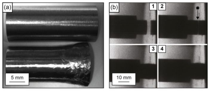
Figure 11: (a) CP titanium projectile before and after deformation. (b) High-speed time lapse photographs at 150,000 frames per second of projectile and sabot impact at a hardened steel target. The photo sequence is 1–4. The impact face is shown in photograph No. 2 with an asterisk (courtesy of Dr Steven Lainé)
By comparison, cylinders of Ti-6Al-4V fired at the same speed as the CP titanium did not always maintain integrity (i.e., they broke up), whereas cylinders of Ti-6Al-4V fired at 200 m s−1 did always maintain integrity. This is because Ti-6Al-4V has a higher dynamic yield strength than CP titanium, but it is noticeably less tough. Therefore, in such projectile experiments, Ti-6Al-4V is observed to be less ductile than CP titanium.
Other h.c.p. metals such as magnesium, zinc and beryllium are hot worked during deformation processing operations, either in tension or in compression, to be able to achieve general plastic shape changes. If they are not hot worked, they are likely to fail by brittle fracture.
Ceramics
Ceramics have the same toughness in compression as they do in tension, so that they exhibit brittle fracture in compression when they fail. However, the significant difference between the behaviour of ceramics in tension and the behaviour of ceramics in compression is that in compression the failure strength is much higher than in tension, typically by a factor of ten or more.
This difference in strength is because of the different fracture mechanisms involved in tension and compression. In compression, fracture arises from the coalescence of many microcracks inclined at a significant angle to the loading axis, whereas in tension fracture is facilitated by the growth of cracks or flaws oriented perpendicular to the loading axis. Fracture in tension arises through the unstable catastrophic propagation of cracks, whereas the coalescence in compression of many microcracks is a relatively more gradual and stable process leading to eventual failure. Typical failure patterns in concrete are shown in Figure 12.
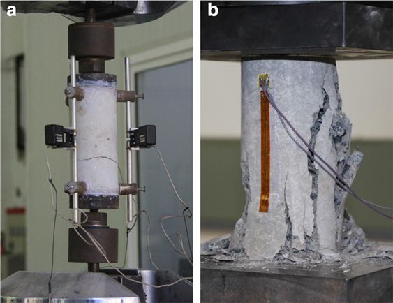
Figure 12: Typical failure patterns of the laboratory tests. (a) Typical failure pattern under tension, (b) typical failure pattern under compression. From https://doi.org/10.1186/s40069-018-0292-1 (CC BY)
A simple way of appreciating how ceramics fail in compression is to indent a ceramic with a hard material such as a Vickers diamond indenter. Cracks produced at the corners of the indentation will not propagate catastrophically, but will instead stop some distance away from the corners, as shown in Figure 13. Laminated glass used for car windscreens behaves in a similar manner – sharp particles impacting the windscreen will cause indentation and local crack formation, with some removal of glass at the impact site. However, the windscreen as a whole will maintain integrity, and the windscreen will only have to be replaced if the diameter of the cracked region is above a specified threshold length. A "chip" in a windscreen is shown in Figure 14.

Figure 13: (a) Surface view (top down) and (b) cross sectional (side on) view of quasi-static 0.5 kgf Vickers indents in an oxide glass. From https://doi.org/10.3389/fmats.2017.00004 (CC BY)

Figure 14: A "chip" in a windscreen. Possibly resulting from two points of contact, there are cracks in the first layer of glass radiating outwards. Delamination of the layers can be seen faintly between the radial cracks. From https://www.flickr.com/photos/18231462@N00/2317641913 (CC BY)
The high failure strength of ceramics in compression, typically 1 GPa or more, is widely used in civil engineering in building design when using construction materials such as bricks, stone, glass, and concrete.
Fibre-reinforced composites
As with metals and ceramics, there are no additional toughening mechanisms in compression in addition to those which operate in tension.
In compression, the principal failure modes of fibre-reinforced composites are fibre kinking, matrix splitting and fibre/matrix debonding. Matrix splitting arises when the matrix splits parallel to the fibres. Useful testing configurations used to examine the behaviour of fibre-reinforced composites under compression are tubes and plates.
In axial compression, the most common form of failure is fibre kinking. A kink band is shown in Figure 15.
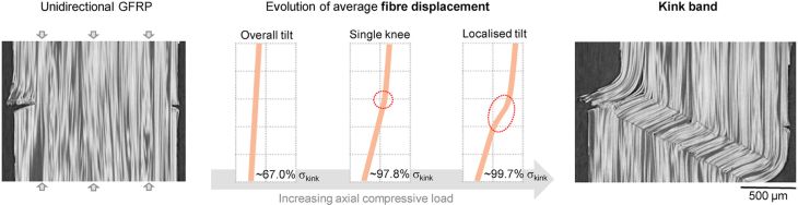
Figure 15: Section of a glass fibre-epoxy composite after failure under uniaxial compression, showing a kink band on the right-hand side. From https://www.sciencedirect.com/science/article/pii/S0266353821002852?via%3Dihub (CC BY)
The kink has formed as a region of the composite has sheared over, allowing external work to be done. This can be considered compressive failure. If the composite has not already failed catastrophically, it is very likely to fail at this point if tension were subsequently applied. Prediction of the applied stress at formation is based on the schematic in Figure 16.
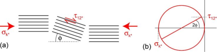
Figure 16: Schematic of stresses and fibre alignments at failure, with a Mohr’s circle
The kink band forms when the \( \tau _{\text{12}} \) stress component has reached some critical value, \( \tau _{\text{12}}^* \). The band will form in some region that happens to have somewhat misaligned fibres because of imperfect processing. Consider a region initially misaligned by an angle φ0. Mohr’s circle allows the relatively straightforward determination of the shear stress, as shown in Figure 16(b). The shear stress will cause some more elastic deformation, rotating the region somewhat further, so the initial misalignment of φ0 becomes φ, increasing the shear component. Failure occurs when the stress has risen sufficiently.
From Mohr’s circle, at the onset of the kink band: \[ \tan 2\varphi = \frac{{\tau _{\text{12}}^*}}{{{\sigma _{\text{k*}}}/2}} \] where \( \sigma _{\text{k*}} \) is the kinking stress, and \( \tau _{\text{12}}^* \) is the critical value of the shear stress required to cause the kinking. If φ is small (a few degrees or so), then the small angle approximation can be used. Expressing φ in radians, tan 2φ ≈ 2φ, so that: \[ {\sigma _{\text{k}*}} = \frac{{\tau _{\text{12}}^*}}{\varphi } \]
The shear moduli are relevant. Some typical values might be \( {G_{\rm{m}}} \) = 1.3 GPa and \( {G_{\rm{f}}} \) = 14 GPa for the matrix and fibres, respectively. Using the Reuss equal stress approximation for composites (See Stiffness of Long Fibre Composites), the shear modulus of the composite, \( {G_{\rm{12}}} \), is \[ {G_{12}} = {\left( {\frac{{{V_{\rm{f}}}}}{{{G_{\rm{f}}}}} + \frac{{1 - {V_{\rm{f}}}}}{{{G_{\rm{m}}}}}} \right)^{ - 1}} \] for a volume fraction of fibres \( {V_{\rm{f}}} \). This gives a composite shear modulus of around 3 GPa. The angle φ can be split into the original misalignment and the additional rotation due to the shear stress. For small angles, this additional rotation is equal to the shear strain, \( \tau _{12}^*/{G_{12}} \). Therefore,
\[ {\sigma _{\text{k}*}} = \frac{{\tau _{12}^*}}{\varphi } \approx \frac{{\tau _{12}^*}}{{{\varphi _0} + \frac{{\tau _{12}^*}}{{{G_{12}}}}}} = {\left( {\frac{{{\varphi _0}}}{{\tau _{12}^*}} + \frac{1}{{{G_{12}}}}} \right)^{ - 1}} \]The kinking stress can be plotted as a function of misalignment, as shown in Figure 17. Depending on the exact critical shear stress, the composite can be very sensitive to the initial alignment of the fibres, so during manufacture, the waviness of the fibres is significant, with poorly aligned fibres giving poor compressive strength.
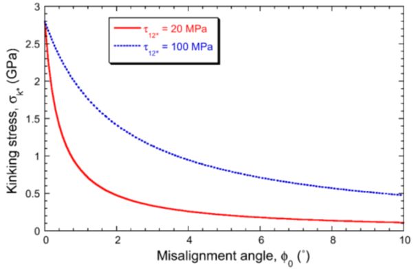
Figure 17: Predicted kinking stress as a function of misalignment angle, for epoxy-60wt% carbon composites, with two different interfacial shear strengths
In seasoned wood used for structural applications there is a cellular structure that has voids. The voids make it easier for the fibres to shear over in this way, so kink bands form more easily, and wood is particularly weak in compression.
Compressive failure when it occurs will be catastrophic in terms of the load-bearing capacity of the fibre-reinforced material, so that just as for ceramics, some material will be ejected from the failure site and the material will no longer be fit for purpose. Frustrated tennis players who smash their rackets against a hard surface and cause compressive failure of the fibre-reinforced composite tennis racket frame help to demonstrate this very point, as shown here.
Further reading
T.W. Clyne and J.E. Campbell, 2021, Testing of the plastic deformation of metals, Cambridge University Press.
M.F. Ashby and S.D. Hallam, 1986, The failure of brittle solids containing small cracks under compressive stress states, Acta Metallurgica 34, 497-510.
M.H. Jensen, 1999, Models of failure in compression of layered materials, Mechanics of Materials, 31, 553-564.
M. Knops, 2010, Analysis of failure in fiber polymer laminates: the theory of Alfred Puck, Springer-Verlag, Berlin.
M. Benamira, C. Hochard and A. Haiahem, 2011, Behaviour to failure of fibre mat reinforced composite under combined loading conditions, Composites: Part B, 42, 1412-1419.