Note: DoITPoMS Teaching and Learning Packages are intended to be used interactively at a computer! This print-friendly version of the TLP is provided for convenience, but does not display all the content of the TLP. For example, any video clips and answers to questions are missing. The formatting (page breaks, etc) of the printed version is unpredictable and highly dependent on your browser.
Contents
Main pages
Additional pages
Aims
On completion of this TLP you should:
- Understand the concept of toughness
- Understand why we toughen materials
- Know the commonly used methods of toughening materials
Before you start
It would be useful to look at the following TLPs:
- Brittle Fracture
- Superelasticity and Shape Memory Alloys
- Stress Analysis and Mohr’s Circle
- Mechanics of Fibre-reinforced Composites
Introduction
Toughness is the ability of a material to absorb energy from impact or applied stresses and deform plastically without fracture. The tougher a material is, the more it can deform plastically, thereby dissipating energy before failure.
Ceramics will typically fail by brittle fracture. The fracture toughness of ceramics, and therefore the failure stress, is increased by mechanisms that slow crack growth by requiring more energy for crack propagation.
In the video below, samples of various commercial chocolate bars are impact tested. Without the samples in place, the pendulum seen in these experiments is free to swing after being released from a predetermined height, and no energy is lost. With the chocolate bars in place at the bottom of the pendulum swing, energy is absorbed, depending on the sample of particular chocolate bar and its temperature: room temperature (20 °C) or liquid nitrogen temperature (−196 °C) in these experiments.
The percentage of energy lost is determined by the height reached by the pendulum after it has interacted with the chocolate bar. The greater the energy lost by the pendulum, the tougher the chocolate bar.
Five commercial chocolate bars were tested in the video below: Sainsbury's 72% Cocoa, Sainsbury's 55% Cocoa, Cadbury's Dairy Milk, Cadbury's Fruit and Nut, and Snickers. A standard sample size was taken to be one row of sharing size chocolate bar.
Impact testing of chocolate
These results demonstrate the range of toughness exhibited by these chocolate products as a function of temperature. They agree with everyday experience: at 20 °C, chocolate bars high in cocoa are much easier to snap in two than a bar of Snickers, and the higher the cocoa content, the easier chocolate bars are to snap. Putting chocolate into the freezer compartment of a refrigerator makes it far more easy to snap cleanly in two than leaving it outside to warm up in the sun. Indeed, if chocolate becomes too warm in the sun, it is almost impossible to snap in two!
We can conclude that for chocolate, toughness depends on composition/structure of the chocolate product and also that some toughening processes are thermally activated.
For further information see Toughness of chocolate food products.
Ductile failure
In ductile materials, failure is preceded by necking. This is common in most metals at room temperature. This instability is due to the rate of increase in the true stress caused by the reducing cross section exceeding the rate of work hardening as the material is plastically deformed.
Considère’s Construction for the onset of necking is discussed in the Mechanical Testing of Metals TLP.
Plastic deformation, particularly under tension, can easily open up voids at interfaces, inclusions or precipitates. The final fracture surface can consist almost entirely of voids. Microvoid coalescence in the neck leads to crack formation and fracture of the material.
At the edges, away from the voids, the material may fail entirely by plasticity. Fracture follows the line of greatest plasticity, leaving a 45° surface since maximum shear occurs at 45° to the applied stress (consider Mohr’s circle).
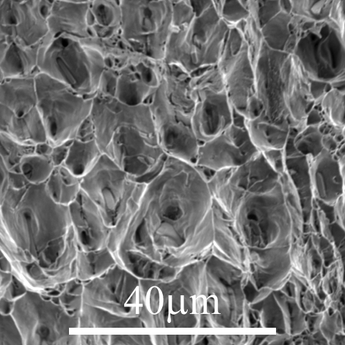
Figure 1: Micrograph 128 from DoITPoMS library - Rough surface of an Al–Mg–Si alloy, failed through microvoid coalescence
In brittle fracture, failure can be hard to predict due to spontaneous and rapid crack propagation. There is no time to replace parts before catastrophic failure occurs. Tougher materials that fail via ductile fracture are favourable due to the ‘warning sign’ of plastic deformation: the crack propagates slowly, absorbing large amounts of energy before fracture.
Failure occurs from flaws in the material. Any surface contact, even between flat surfaces, introduces flaws to a material, assuming there is an edge to at least one of the surfaces. A brittle material used for strength will develop flaws, unable to absorb much energy before fracture. Instead of removing flaws, which is highly impractical, we require mechanisms to improve toughness to prevent crack formation and subsequent growth.
Transformation toughening
Tough materials can absorb energy at or around the crack tip, by processes such as plastic flow in metals. Usually ceramics cannot do this to a significant degree, so fail by brittle fracture. However, some ceramics show a stress-induced martensitic transformation. This occurs in a local region (or zone) around the crack tip where stress is concentrated; the far-field stress is insufficient to cause the transformation. As the crack grows, this zone moves through the material.
This martensitic transformation requires energy to be absorbed in order to overcome the energy barrier associated with forming the new phase. Further, if there is a volume increase from the high temperature (austenite) phase to the martensite phase, the local tensile stress at the crack tip will decrease. Both factors hinder crack progression through the material and therefore increase the toughness, leading to the concept of transformation toughening.
Zirconia is a ceramic that can undergo transformation toughening by using a tetragonal to monoclinic martensitic transformation provided it fits the following conditions:
- At the operating temperature the tetragonal phase is metastable, so the work done is not recoverable
- The energy barrier to transformation is small
- A reasonable strain is associated with the transformation
- Work can be done ahead of the crack tip which leads to increased fracture resistance
- There is a volume increase
- The operating temperature needs to be below the martensitic transformation temperature otherwise no toughening can occur by transformation
Assuming no constraints, i.e., assuming (i) the surface energies of the tetragonal and monoclinic phases are identical, (ii) that the condition for transformation is independent of the size of the region to be transformed, and (iii) that the volumes of the two phases for a given mass are identical, the driving force of the transformation per unit volume (of the tetragonal phase) is:
\[ \Delta {U^{(\text{t} \to \text{m})}} = \Delta G = {G_ \text{m}} - {G_ \text{t}}\]
\[ {\Delta G} = {\Delta H} - {T\Delta S} \]
where \( G_ \text{m} \) and \( G_ \text{t} \) are the Gibbs free energy in joules per unit volume of the monoclinic and tetragonal phase respectively.
We can assume that enthalpy does not vary significantly with temperature; this is a very reasonable approximation. The equilibrium temperature will be when \( \Delta G = 0 \) because we can ignore any barriers to the phase transformation such as the surface energy. The graph below shows how the driving force changes with temperature.
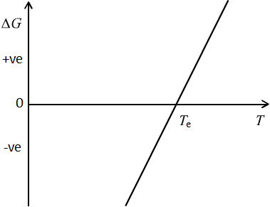
Figure 2: Gibbs free energy per unit volume as a function of temperature
Above the equilibrium temperature, \( {T_ \text{e}} \), \( \Delta G \) is positive because the tetragonal phase is the stable phase. Below the equilibrium temperature \( \Delta G \) is negative because the monoclinic phase is the stable phase. The gradient of the line, \( -\Delta S \), is therefore positive, and so \( \Delta S \) is negative, as is therefore \( \Delta H \), because at \( {T_ \text{e}} \), \( \Delta H = T_ \text{e}\Delta S \). This is a useful check: on cooling through the transformation temperature, \( \Delta H \) will be negative if it is a first order phase transition, consistent with latent heat being released. Hence, \( \Delta S \) is negative.
Effect of constraints
In the equations on the previous page, it was assumed that the surface energies of the two phases are identical, so that they have no effect in the energy balance, but this is not the case. The size of the crystal must be included in the driving force which is shown below.
\[ \Delta {U^{\text{t} \to \text{m}}} = \frac{4}{3}\pi {r^3}\Delta G + 4\pi {r^2}\Delta \gamma \]
where \( \Delta U \) is the total free energy change in units of joules (J), \( r \) is the radius of the monoclinic crystal produced, assumed here to be spherical, and \( \Delta \gamma \) is the difference in surface energies in J m−2 of the monoclinic and tetragonal phases.
\( \Delta S \) remains unchanged. If we define the equilibrium transformation temperature in the absence of constraint to be \( T_ \text{e} \), \( \Delta H = T_ \text{e} \Delta S \). Therefore, at a temperature \( T \) below \( T_ \text{e} \), \( \Delta G = (T_ \text{e} - T) \Delta S \).
Setting \( \Delta {U^{\text{t} \to \text{m}}} \) to be zero, because martensitic transformations are spontaneous and do not require a classical nucleation and growth approach to analyse their transformation like liquid → solid and other solid → solid phase transformations, we find that
\[ \frac{4}{3}(T_\text{e}-T) \pi{r^3}\Delta S^{{\text{t} \to \text{m}}} + 4\pi {r^2}\Delta \gamma = 0 \]
This defines a lower temperature, \( T = T' \) for the transformation of a particle of size \( r \) to transform, where
\[ T' = T_\text{e} - \frac{3\Delta \gamma}{r\left| \Delta S\right|} \]so that, in words, the temperature at which a tetragonal zirconia particle will transform spontaneously to being a monoclinic zirconia particle is determined by its size.
Hence, if the zirconia particles are embedded in an untransforming matrix such as alumina, and if there is no constraint by the surrounding matrix (which we examine below), then on cooling below the equilibrium transformation temperature to (say) room temperature, we can predict that large tetragonal particles will transform, but small particles will not.
For the martensitic transformation in zirconia, \( T_ \text{e} \) is 1240 °C, \( \Delta \gamma \) is 3 J m−2 and \( \Delta S \) = −120 kJ m−3 K−1, so that for \( T' \) to be room temperature (20 °C), \( r \) is 61.5 nm. Therefore, without considering constraint, it can be deduced that only very small particles would remain untransformed at room temperature.
In a real physical situation, the situation is even more complex. The equation above is for a single crystal transforming in a matrix which we assume does not apply any constraint. In practice, there will be elastic constraint from this matrix which will inhibit the martensitic transformation. This will manifest itself in an additional strain energy term in the energy balance:
\[\Delta {U_E} = \frac{1}{6}k{\theta ^2}V\]
where \( V \) is the volume, \( \theta \) is the volumetric strain, ⅙ is just a geometric factor and \( k \) is a function of the elastic constants given by:
\[ k = 2\frac{{{E_\text{M}}{E_\text{p}}}}{{{E_\text{M}} + {E_\text{p}}}} \]
where \( E_\text{M} \) is the stiffness of the matrix and \( E_\text{p} \) is the stiffness of the particle. This further shifts the line to the left in the graph shown in the animation further down the page.
As before, \( \Delta S \) remains unchanged. The spontaneous transformation \( T'' \) for a particle of size \( r \) is now:
\[ T'' = T_\text{e} - \left| \frac{3 \Delta \gamma}{r \Delta S} \right| - \left| \frac{k \theta^2}{6 \Delta S} \right| \]
Therefore, the effect of strain energy is to make the spontaneous transformation of particles of a particular size less likely.
Transformation energy
If sufficient stress is applied at room temperature to an untransformed tetragonal particle which has been prevented from transforming because of its size and the degree of volumetric strain, the transformation to the monoclinic phase can occur.
The work required for this is seen in the graph above. Using the difference between \( T'' \) and \( T \) with the gradient
\[ \Delta W = - {f}\Delta {S}\left( {{T} - {T''}} \right) \]
- Stress must act to reduce the misfit of the transformation, because there is a volume expansion when going from the tetragonal form of zirconia to the monoclinic form
- The hydrostatic component of the stress (the component of the stress tensor associated with a change in volume, i.e., the dilatational component) must be tensile.
Cracks have high stresses at the tip. If the far field stress is tensile, then the crack tip must also have a hydrostatic tensile stress, \(\sigma_\text{H}\). Using tensors in a uniaxial set up:
\[ {\sigma_\text{H}} = \frac{1}{3}{\rm{\;}}{\sigma_0}{\rm{\;\;\;\;\;\;\;\;\;\;for\;a\;stress\;tensor\;\;\;\;}}\left( {\begin{array}{*{20}{c}}
{{\sigma _0}}&0&0\\
0&0&0\\
0&0&0
\end{array}} \right) \]
or, in terms of strain, if there is a volumetric (hydrostatic) strain \( \theta \), the linear strain along a particular axis is
\[ \varepsilon = \frac{1}{3}\;\theta \]
Therefore, the work, \( \Delta W \), associated with the dilatational component of the martensitic phase transformation for a volume fraction of particles, \( f \), is
\[ \Delta W = f{\sigma_\text{H}}\theta = f{\sigma_0}\varepsilon \]
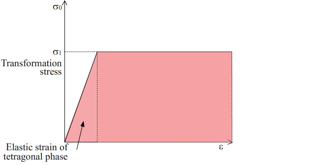
Figure 3: Uniaxial Stress - linear strain graph of the transformation from the tetragonal phase to the monoclinic phase in zirconia. The area shaded in pink is the energy absorbed. The elastic strain energy contribution of the tetragonal phase is small relative to the work done in causing the martensitic transformation of this phase to the monoclinic phase
Hence, for an applied uniaxial stress \( \sigma_{\text{t}} \) where the critical linear strain is \( \varepsilon_{\text{t}} \) (so that the volumetric strain is \( 3\varepsilon_{\text{t}} \)), particles which would have transformed spontaneously at \( T'' \) will now transform at a temperature \( T \) defined by the relationship
\[ {\sigma_\text{t}} = - \frac{{\Delta S\left( {T - T''} \right)}}{{{\varepsilon_\text{t}}}} \]
This applied uniaxial stress will act to toughen the material if the martensitic transformation is not reversible on removal of the stress, so that the work per unit volume put into the material is absorbed by the material.
Contribution to fracture resistance
If the far field stress is insufficient to cause the tetragonal to monoclinic phase transformation, then only a local region near the crack tip will transform. The size of the transformed zone can be calculated by working out the stress distribution ahead of the crack tip which is given by:
\[ \sigma \left( r \right) = \frac{K}{{\sqrt {2\pi r} }} \]
where \( K \) is the stress intensity factor and \( r \) is the distance from the crack tip. For a sharp surface crack of length \( a \) and an applied stress, \( \sigma_\text{app}, K = 1.12\sigma_\text{app}\sqrt{\pi a} \). For other situations, 1.12 is replaced by a more general geometric factor, \( Y, \) dependent on the specific situation.
We can rearrange the equation for the size of the transformed zone to show that when the transformation stress, \( \sigma_\text{t} \), has been reached in the vicinity of the crack tip, the size of the transformation zone, \( r_\text{t} \), is given by an expression of the form
\[ {r_\text{t}} = A{\left( {\frac{K}{{{\sigma_\text{t}}}}} \right)^2} \]
where \( A \) is a geometric constant.
If we take this distance to be the extent of the transformation either side of the crack plane, then for a unit area of crack plane the work done in causing the martensitic transformation, \( \Delta {\Gamma_\text{t}} \), will produce the extra resistance to fracture:
\[ \Delta {\Gamma_\text{t}} = 2{r_\text{t}} f {\sigma_\text{t}}{\varepsilon_\text{t}} \]
Assuming that \( f \) remains constant and recognising that \( \varepsilon_\text{t} \) is a constant, it follows that
\[ \Delta {\Gamma_\text{t}} \propto \frac{{{\sigma_\text{t}}}}{{\sigma_\text{t}^2}} = \frac{1}{{{\sigma_\text{t}}}} \]
Therefore, the lower the transformation stress required, \( \sigma_\text{t} \), the larger the degree of resistance is to fracture, and therefore, the more tough is the material.
Making tough zirconia
It is difficult to make zirconia that has a metastable tetragonal phase at room temperature. Very small grains are required because otherwise the grains will spontaneously transform into the stable monoclinic phase.
There is more than one way to make zirconia with a metastable tetragonal phase. The first method is to add alloying additions which lower the cubic solid solution temperature and then follow a particular heat treatment schedule.
One suitable alloying addition is magnesia, MgO. As can be seen in the phase diagram below in Figure 4, the addition of MgO stabilises the cubic solid solution phase to lower temperatures, keeping the tetragonal to monoclinic equilibrium transformation temperature unaffected. The diffusion kinetics of the eutectoid transformation of this cubic phase to tetragonal zirconia and MgO at 1400 °C are very sluggish; this enables the cubic phase to be retained down to room temperature as a metastable matrix phase within which there are fine second phase tetragonal precipitates. The material has the acronym PSZ - partially stabilised zirconia.
The following thermal process can be used to form metastable tetragonal grains:
- Solution treat in the cubic phase field
- Quench to a suitable temperature in the cubic/tetragonal two-phase field
- Age at this temperature to produce tetragonal precipitates. Initially these precipitates form as fine Guinier-Preston (GP) zones.
- Coarsen these GP zones to produce lenticular tetragonal zirconia precipitates only a few nm in size
- Cool to room temperature to prevent the eutectoid decomposition of the cubic zirconia matrix phase
The resulting microstructure is one where the lenticular tetragonal particles are metastable and will not have transformed spontaneously into the stable monoclinic zirconia phase
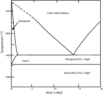
Figure 4: Zirconia-magnesia phase diagram
A second way of making tough zirconia is to add alloying additions which change the transformation temperature. Additions of yttria, Y2O3, and ceria, CeO2, at the level of a few mole per cent are often used to stabilise the tetragonal phase down to room temperature. Yttria-tetragonal zirconia polycrystals (Y-TZP) are commercial ceramics which make use of this ability to stabilise the tetragonal phase down to room temperature.
A third way of making tough zirconia is to increase the elastic resistance to transformation. This can be achieved by having a stiff surrounding matrix within which tetragonal zirconia particles are dispersed (see the equation for \( k \) in the section Effect of constraints). An example of this is zirconia-toughened alumina (ZTA) in which tetragonal zirconia particles are dispersed in a stiff polycrystalline alumina matrix (Figure 5). Alumina is twice as stiff as zirconia. For such ceramics, the matrix must having the following requirements:
- A low solubility for zirconia
- No chemical reactions / intermediate phase formation
- A stiffness higher than zirconia
- It must also be cheaper than zirconia
Other examples of this family of ceramics are mullite-ZrO2, NiAl-ZrO2 and MoSi2-ZrO2.
ZTA is used in applications such as cutting tools for wood and steel where good wear resistance is required, and where very high temperatures are not reached on the surface of the cutting tool.
Figure 5: Micrograph 195 from the DoITPoMS library - Micrograph of ZTA
TRIP and TWIP steels
In addition to dislocation motion, metals may also deform plastically by other mechanisms. One mechanism is a stress-induced transformation of the crystal structure and a second mechanism is stress-induced twinning of the crystal structure. By suitable alloying additions to plain Fe−C steels, these mechanisms can be exploited. These steels are known as TRIP (TRansformation Induced Plasticity) and TWIP (TWinning Induced Plasticity) steels, respectively.
Transformation-induced plasticity steel: TRIP steel
An example of a TRIP steel is Fe with 0.2wt% C, 2wt% Mn and 2wt% Si. This has a ferrite \( \alpha \) matrix with >5% retained austenite. The microstructure also has martensite and bainite in small amounts. As there is a significant volume fraction of retained austenite, it is possible to induce the displacive transformation of the austenite to martensite by straining the steel. The transformation has a large associated transformation strain and allows plastic strains up to 35% to be reached without sacrificing strength.
The relative free energy of the face-centred cubic \( \gamma \) phase (austenite) and the sheared body centred tetragonal martensite phase are shown in Figure 6. On cooling, the austenite does not spontaneously transform when the two free energies are equal (the temperature, \( T_{\text{eq}} \), where the two lines cross) because there are significant energy barriers (strain energy and surface energy both rise when the material transforms). Instead, a significant undercooling is required to cause martensite to form. The proportion of martensite that transforms varies continuously with the cooling below the equilibrium temperature. The onset of martensite formation is denoted \( M_{\text{s}} \), and the end of martensite formation is denoted \( M_{\text{f}} \).
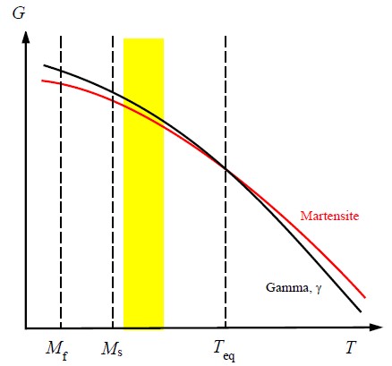
Figure 6: Gibbs free energy, \( G \), of martensite and \( \gamma \) as a function of temperature
In order to exhibit TRIP behaviour, the austenite should be retained, so the service temperature (usually the ambient temperature) must be above \( M_{\text{s}} \), and the barrier to the transformation should not be too large, otherwise the applied stress will not be sufficient to trigger the transformation. Thus, the temperature should be only just above \( M_{\text{s}} \), so that it is within the temperature range defined by the filled yellow rectangle shown in Figure 6. Austenite retained in this way is metastable and if provided with some energy (e.g., by an applied stress) to overcome the barrier, the austenite may transform to martensite. If this occurs, the transformation is irreversible and significant amounts of energy are absorbed.
In addition to the direct work absorbed in inducing the transformation, there is also a contribution to toughness of the material through the relief of locally concentrated stresses, an enhancement of the work hardening rate and allowing deformation to occur homogenously throughout the material to absorb more energy. These effects arise because the strong martensite forms in the regions experiencing the highest strain, locally reinforcing the material, and spreading the deformation to other regions. If the retained austenite is a minor proportion of the microstructure, then the material is sometimes known as TRIP-assisted steel.
TRIP steels, such as Fe−0.2wt% C−2wt% Mn−2wt% Si, are alloyed and heat treated carefully to produce the desired amount of retained austenite and martensite start temperature, \( M_{\text{s}} \), so that toughening is maximised. In particular, the addition of Si suppresses the formation of Fe3C carbides, raising the carbon concentration in the remaining austenite and preventing its transformation to ferrite. Since the austenite phase is stabilised, some will be retained when cooled to room temperature. A TRIP-assisted steel microstructure is shown in Figure 7.
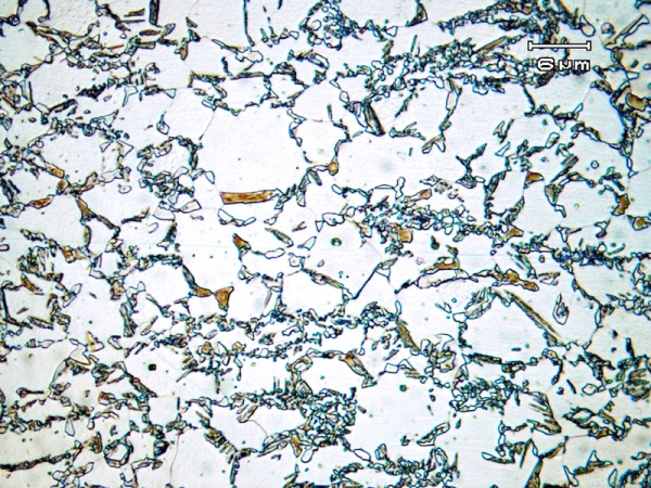
Figure 7: TRIP steel annealed at 775°C for 5 mins and then hold at 400°C for 40s for austenite stabilization The largest grains are ferrite, the darker regions are bainitic, and the smaller white grains are the retained austenite, which will transform to martensite when a stress is applied (micrograph 740 from the micrograph library).
During subsequent deformation, the strain at which the austenite starts to transform is controlled by the carbon content.
If the carbon content is relatively low, the steel is inherently quite formable and the transformation to martensite will occur almost immediately, which increases the work hardening rate because martensite is hard.
If the carbon content is relatively high, the retained austenite is more stable and will only start to transform to martensite when the strain levels are beyond the strains arising during forming operations. This means the material is particularly tough because the transformation that occurs when excessive stress is applied will absorb energy.
As TRIP steel can absorb significant amounts of energy as it gets deformed when excessive stress is applied, it is often used in cars in crumple zones to help absorb energy if there is a collision, and therefore to help protect the car passengers.
Twinning-induced plasticity steel: TWIP steel
TWIP steels are typically made with 15−30 wt% Mn, 3 wt% Si and 3 wt% Al. The reason for such a high Mn content is to ensure the steel has a fully austenitic \( \gamma \) phase microstructure at room temperature.
Mechanical twinning is observed in many materials. This allows the deformation of the material by cooperative shear of a number of planes simultaneously. The result is that potentially very large shear strains are achievable. The distinction between TWIP steels and TRIP steels is that after the shearing of the austenite planes in TWIP steels, the structure is the same austenitic structure, but reoriented relative to the original parent grain.
In TWIP steels this can be exploited by retaining stable austenite to the operating temperature, via the addition of the austenite stabiliser manganese. The addition of some aluminium and silicon reduces the density and helps to control the stacking fault energy to ensure that the material remains as f.c.c. austenite. At high manganese concentrations, the stacking fault energy is sufficiently low that a further TRIP mechanism can occur during deformation, converting the \( \gamma \) phase via a martensitic transformation to the h.c.p. \( \varepsilon \) phase
In \( \gamma \), the twins that form under sufficient stress are {1 1 1}<1 1 2>. The shear strain that this produces is large,\( 1 / \sqrt{2} \) . This is large even compared with transformation strains. This twinning tends to happen simultaneously with the glide of dislocations on the {111} \( \gamma \) planes.
A major advantage of TWIP steels is their f.c.c. austenitic structure. These steels do not exhibit a ductile to brittle transition, even at cryogenic temperatures, and remain ductile even to high strain rates, e.g., 103 s−1.
When plastically worked, twinning occurs in TWIP steels. This twinning increases the work hardening rate of these steels because the twinning boundaries act like grain boundaries, preventing the movement of dislocations. TWIP steels have high ultimate strengths, >1 GPa, and high formability.
Crack deflection
Often in composite materials both elements are quite brittle, so that individually they both have a low fracture toughness. It might therefore be reasonable to expect that the fracture toughness of the composite material would also be low. However, this is not necessarily the case. With careful microstructural design, composites can achieve notably higher levels of toughness than their individual components.
Central to this microstructural design is the ability of the microstructure to cause cracks to deflect away from what would otherwise be rapid crack propagation paths, leading to catastrophic sudden failure. Interfaces between the different components of the composite material are of particular interest in this regard.
For a crack propagating normal to an interface to deflect along the interface, and not continue to propagate through the bulk of the material, the criterion
\[ \frac{{{{\rm{\Gamma }}_\text{i}}}}{{{{\rm{\Gamma }}_\text{bulk}}}} < \frac{1}{{2\pi }} \]
needs to be satisfied, where \( \Gamma_\text{i} \) is the interfacial strain energy release rate ('fracture resistance') and \( \Gamma_\text{bulk} \) is the bulk strain energy release rate / fracture resistance. Click here to see a full derivation for this criterion for crack deflection.
The following animation shows the two ways a crack could grow through a material.
The design of the composite material will therefore enable cracks propagating perpendicular to the interfaces between the different components, as a consequence of a suitable level of applied stress, to be deflected along the interface between the components.
Incorporating such 'weak' interfaces in composite materials is beneficial in increasing their fracture toughness. It also makes their failure 'graceful', rather than catastrophic. A well-designed fibre composite is seen to have a very obvious fibrous fracture surface when a crack has finally propagated across the composite and the whole fracture surface has been exposed
Crack deflection is used in laminated materials to make them tough. An example of this is laminated SiC with weak graphite interlayers between each SiC lamina. The graphite interlayers are oriented so that the individual sheets of graphite within the interlayers lie preferentially parallel to the laminae, rather than perpendicular to them. As the graphs and diagrams show schematically in the animation below, significantly more energy can be absorbed by the laminated SiC in comparison with a solid block of SiC.
Laminated glasses are very popular to use because of their high toughness and their transparency to visible light. Windscreens of modern cars are made from laminated glass. Small stones thrown up from the road impacting windscreens behave like indenters, leaving behind a relatively small volume of damage on the windscreen, rather than the windscreen shattering into thousands of small pieces, as happens with toughened glass when hit sufficiently hard by a small stone.
It is common to see laminated glass being used in tourist attractions. Examples are staircases in various Apple stores worldwide, the Grand Canyon viewing platform in the U.S.A., the glass walkway on Tianmen Mountain in China, the glass floor at the CN Tower in Toronto, Canada and the revolving glass floor at the Space Needle in Seattle in the U.S.A.

Glass walkway on Tianmen Mountain (Wikimedia Commons)
Fibre pull out
Long
When a crack propagates through a material reinforced with long fibres there are many processes that happen. For the crack to propagate transversely to an applied stress parallel to the length of the fibres, each fibre will have to break; this usually occurs somewhere along the fibre where there is a relatively large flaw because the strength of the fibre is greater than the strength of the material it is reinforcing. This means that for the crack to propagate, the surfaces between the crack and where the fibre has broken will need to to debond to enable the fibre to be extracted. Both of these processes absorb energy, helping to toughen the composite.
An issue with long fibre composites is that they are difficult to produce. For fibres to achieve high toughening they must be packed tightly. However, this means powder routes for a ceramic matrix are not the best choice because the powder is unlikely to fill the space between fibres very efficiently. This is likely to create a very uneven composite matrix. One way of overcoming this problem is to produce the matrix as a glass which is then devitrified, such as in Figure 8 below. Here, the matrix has crystallised as a magnesium aluminosilicate.
A second potential problem with such processing routes is that the high sintering temperatures needed are likely to cause large stresses at the matrix-fibre interfaces when cooled because of different thermal expansion coefficients of the fibre and the matrix. This can potentially lead to failure along the matrix-fibre interfaces immediately upon cooling.
Other ways to produce long fibre ceramic composites are to use liquid or gaseous precursor processing routes. In these routes, the resultant ceramic is more likely to deposit on the fibres near the surface of the composite, rather than penetrate into the interior of the composite. This means that it can often take several infiltration steps to produce sufficient ceramic in the middle of the composite. This repeated infiltration is expensive and time consuming, making these processes impractical in industry for anything other than niche applications where the cost is not a major factor. A second consideration for these processing routes is that because the temperatures involved in the breakdown of the precursors to form the ceramics are relatively modest, such composites are unlikely to be able to be used at temperatures > 1000 °C because of thermal mismatch considerations. One notable exception is that of SiC fibres in a SiC matrix: although the matrix is not fully dense, this does not have thermal mismatch problems.
Long fibre polymer matrix composites are more easily processed. For example, carbon fibre-reinforced epoxy resin matrix composites typically require curing temperatures less than 160 °C. Such composites are used in a wide variety of sports, automotive and aerospace applications where light, stiff and tough materials are required for ambient temperature use.
Short
With short fibres, the amount of toughening is limited by the length of the fibres, rather than the strength of the fibres, as in long fibre composites. The main advantage of short fibres is that there is not much alteration required during processing. For example, in alumina reinforced with SiC, the short fibres ('whiskers') are mixed in before hot pressing. Alumina reinforced with SiC whiskers is often used for cutting tools. Such tools have good wear resistance because SiC is hard and sufficiently tough. As well as this advantage, cutting tools tend to get hot during use. This helps to oxidise the SiC into SiO2. This is good because SiO2 is also hard, which is also useful for the cutting ability of the tool.
However, as the material is still quite brittle, there is the possibility that small particles could break off the cutting tools in service. If these particles are the SiC whiskers, this has the potential to be dangerous because such small fibres tend to be toxic. For example, asbestos is a naturally occurring fibrous silicate mineral which causes asbestosis if inhaled over a prolonged period, leading eventually to death. Therefore, suitable ventilation precautions must be used in both the processing and use of such composite materials.
Elongated grains
Some toughening can be provided to a ceramic if the microstructure can be sufficiently modified in situ. This requires making grains with elongated structures that promote crack deflection and fibre-like pull out. These grains can also act to bridge gaps ('cracks'), similar to the behaviour of fibres.
An example of a material that undergoes such toughening is silicon nitride, Si3N4. In silicon nitride the crystals are anisotropic so there are anisotropic surface energies that lead to preferred growth directions. A powder compact can use a liquid phase to help create the desired microstructure. \( \alpha \)-Si3N4 is mixed with \( \beta \)-Si3N4 (5 wt%) and either Al2O3 or Y2O3 (5 wt%). During consolidation at high temperature (typically around 1700 °C) by hot pressing, the oxides melt and form a liquid phase which acts as a sintering aid. The \( \alpha \) crystals dissolve in preference to the \( \beta \) crystals and reprecipitate out from the liquid as the \( \beta \) phase. The newly precipitated \( \beta \) phase is highly anisotropic so that \( \beta \)-rods form, with the original \( \beta \) crystals being used to help nucleate these new rods. After suitable time at this high temperature, the ceramic is cooled quickly enough so that the oxide-rich liquid does not have time to crystallise and instead forms a glass. With careful choice of starting materials in the initial powder compact, the final microstructure can be formed of \( \beta \)-Si3N4 rods with nanometre thick residual grain boundary glassy phases and only small amounts of residual equiaxed grains of \( \alpha \)-Si3N4.
The glass at the boundaries has a lower fracture resistance than the \( \beta \)-Si3N4, and so it is able to deflect growing cracks around these elongated grains. This process acts to toughen the material by crack deflection and fibre pull out, similar to the behaviour of fibres in a composite material used to provide toughness.
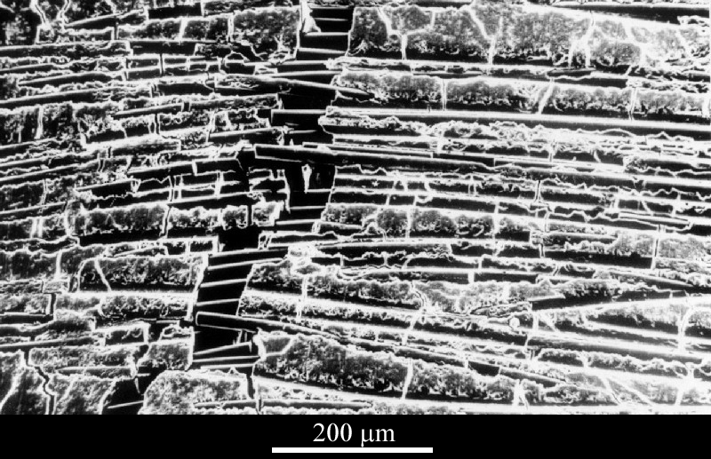
Figure 8: Micrograph 548 from the DoITPoMS library: SiC fibre-reinforced magnesium aluminosilicate where fibres are bridging the crack
For more information on types of fibres used in composites, click here.
How do fibres affect the Weibull modulus?
In fibre-reinforced polymers, such as carbon fibre-reinforced epoxy resin, and in fibre-reinforced ceramics, the most likely cause of failure is brittle fracture. Therefore, for such materials, a Weibull statistical approach can be used to assess fracture behaviour - see the relevant Brittle Fracture TLP web page for more information on this method.
For brittle materials, we might expect that for a particular flaw size, \( a \), the fracture strength, \( \sigma _\text{f} \), might increase if the fracture toughness, \( K_\text{Ic} \), increases, through a formula of the general form \({\sigma _\text{f}} = Y \sqrt {K_\text{Ic}/ a} \), where \( Y \) is a geometrical factor. This would suggest that the distribution in failure stresses for a batch of nominally similar brittle fibre-reinforced materials would have the same Weibull modulus as the unreinforced material, with the distribution in failure stresses increasing because \( K_\text{Ic} \), has increased, as shown below in Figure 9.
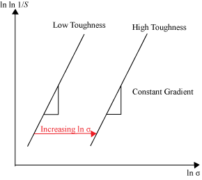
Figure 9: Effect of changing the toughness, \( K_\text{Ic} \), on the Weibull distribution of failure strength, \( \sigma _\text{f} \), of a brittle material. \( S \) is the probability of survival at a particular stress, \( \sigma \).
However, this simple approach ignores the fact that toughness is produced in a fibre-reinforced material by processes such as crack deflection, whereby ligaments in the form of fibres are left behind as a crack grows in the matrix. Hence, the fracture resistance, \( R \), of the material is a function of the crack size, i.e., these fibre-reinforced materials exhibit \( R \)-curve behaviour, as also considered here in the Brittle Fracture TLP.
At very low applied stresses, only very large cracks can grow, and will do so catastrophically; at very high applied stresses, only very small cracks can grow, and if they do, they will also do so catastrophically.
At a narrow range of intermediate applied stresses, the cracks can grow in a stable manner: fibres behind the crack tip cease to help in the bridging of the crack, while fibres ahead of the crack tip will come into effect and help to bridge the crack at the crack tip. Hence, in this narrow range of intermediate applied stresses, the Weibull modulus of the fibre-reinforced material is higher than at low applied stresses and high applied stresses because of this stable crack growth behaviour.
This is all demonstrated in the animation below and in the accompanying schematic diagram in Figure 10.
The addition of fibres alters the Weibull plot with a very high Weibull modulus at the tangent point. For example Si3N4 reinforced with fibres increases its Weibull modulus from around 5 to around 20. An increased Weibull modulus is important as it means the part is much more reliable in service so the safety margin can be made smaller and the device can be used at larger applied stresses. Figure 10 shows how the Weibull modulus changes when fibres are added. There is a sudden increase in the probability of failure for a small range of crack lengths corresponding to the tangent point of the r-curve.
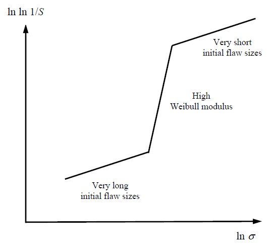
Figure 10: Change in Weibull modulus with stress for fibre-reinforced brittle materials
Toughness in compression
Up to this point in the TLP, we have mainly considered toughness behaviour in tension, such as in the failure of brittle materials like ceramics and the toughening of fibrous materials in tension through fibre pull out. Here, we consider the toughness of metals, ceramics and fibre-reinforced composites in compression.
Metals
In metals, compressive stresses initially cause fully elastic behaviour. As with tensile stresses, the onset of plasticity under compression causes dislocation glide. In f.c.c. metals and b.c.c. metals where five independent slip systems are able to operate to produce a general plastic shape change of a polycrystalline material, the very toughening mechanisms responsible for toughness in tension are the same as those responsible for toughness in compression.
For h.c.p. metals such as titanium and zirconium, for which five independent slip systems do not operate at room temperature, general plastic shape changes are able to occur by a combination of slip and deformation twinning, both in tension and compression. In Figure 11 below, a cylinder of commercial purity (CP) titanium subjected to a very high compressive force and a very high rate of strain by being fired at 250 m s−1 is shown impacting a hardened steel target. The CP titanium cylinders were encased in nylon sabots used to provide a low friction seal with the gas gun used for these experiments. Note how the cylinder has deformed after this experiment, producing a characteristic ‘elephant’s foot’ shape.
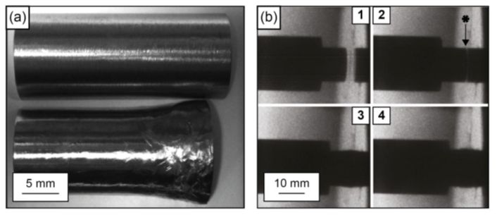
Figure 11: (a) CP titanium projectile before and after deformation. (b) High-speed time lapse photographs at 150,000 frames per second of projectile and sabot impact at a hardened steel target. The photo sequence is 1–4. The impact face is shown in photograph No. 2 with an asterisk (courtesy of Dr Steven Lainé)
By comparison, cylinders of Ti-6Al-4V fired at the same speed as the CP titanium did not always maintain integrity (i.e., they broke up), whereas cylinders of Ti-6Al-4V fired at 200 m s−1 did always maintain integrity. This is because Ti-6Al-4V has a higher dynamic yield strength than CP titanium, but it is noticeably less tough. Therefore, in such projectile experiments, Ti-6Al-4V is observed to be less ductile than CP titanium.
Other h.c.p. metals such as magnesium, zinc and beryllium are hot worked during deformation processing operations, either in tension or in compression, to be able to achieve general plastic shape changes. If they are not hot worked, they are likely to fail by brittle fracture.
Ceramics
Ceramics have the same toughness in compression as they do in tension, so that they exhibit brittle fracture in compression when they fail. However, the significant difference between the behaviour of ceramics in tension and the behaviour of ceramics in compression is that in compression the failure strength is much higher than in tension, typically by a factor of ten or more.
This difference in strength is because of the different fracture mechanisms involved in tension and compression. In compression, fracture arises from the coalescence of many microcracks inclined at a significant angle to the loading axis, whereas in tension fracture is facilitated by the growth of cracks or flaws oriented perpendicular to the loading axis. Fracture in tension arises through the unstable catastrophic propagation of cracks, whereas the coalescence in compression of many microcracks is a relatively more gradual and stable process leading to eventual failure. Typical failure patterns in concrete are shown in Figure 12.
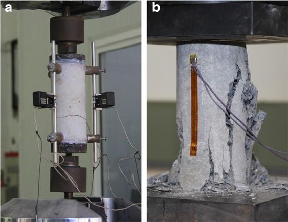
Figure 12: Typical failure patterns of the laboratory tests. (a) Typical failure pattern under tension, (b) typical failure pattern under compression. From https://doi.org/10.1186/s40069-018-0292-1 (CC BY)
A simple way of appreciating how ceramics fail in compression is to indent a ceramic with a hard material such as a Vickers diamond indenter. Cracks produced at the corners of the indentation will not propagate catastrophically, but will instead stop some distance away from the corners, as shown in Figure 13. Laminated glass used for car windscreens behaves in a similar manner – sharp particles impacting the windscreen will cause indentation and local crack formation, with some removal of glass at the impact site. However, the windscreen as a whole will maintain integrity, and the windscreen will only have to be replaced if the diameter of the cracked region is above a specified threshold length. A "chip" in a windscreen is shown in Figure 14.

Figure 13: (a) Surface view (top down) and (b) cross sectional (side on) view of quasi-static 0.5 kgf Vickers indents in an oxide glass. From https://doi.org/10.3389/fmats.2017.00004 (CC BY)

Figure 14: A "chip" in a windscreen. Possibly resulting from two points of contact, there are cracks in the first layer of glass radiating outwards. Delamination of the layers can be seen faintly between the radial cracks. From https://www.flickr.com/photos/18231462@N00/2317641913 (CC BY)
The high failure strength of ceramics in compression, typically 1 GPa or more, is widely used in civil engineering in building design when using construction materials such as bricks, stone, glass, and concrete.
Fibre-reinforced composites
As with metals and ceramics, there are no additional toughening mechanisms in compression in addition to those which operate in tension.
In compression, the principal failure modes of fibre-reinforced composites are fibre kinking, matrix splitting and fibre/matrix debonding. Matrix splitting arises when the matrix splits parallel to the fibres. Useful testing configurations used to examine the behaviour of fibre-reinforced composites under compression are tubes and plates.
In axial compression, the most common form of failure is fibre kinking. A kink band is shown in Figure 15.
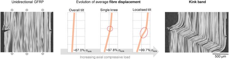
Figure 15: Section of a glass fibre-epoxy composite after failure under uniaxial compression, showing a kink band on the right-hand side. From https://www.sciencedirect.com/science/article/pii/S0266353821002852?via%3Dihub (CC BY)
The kink has formed as a region of the composite has sheared over, allowing external work to be done. This can be considered compressive failure. If the composite has not already failed catastrophically, it is very likely to fail at this point if tension were subsequently applied. Prediction of the applied stress at formation is based on the schematic in Figure 16.
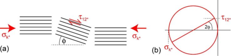
Figure 16: Schematic of stresses and fibre alignments at failure, with a Mohr’s circle
The kink band forms when the \( \tau _{\text{12}} \) stress component has reached some critical value, \( \tau _{\text{12}}^* \). The band will form in some region that happens to have somewhat misaligned fibres because of imperfect processing. Consider a region initially misaligned by an angle φ0. Mohr’s circle allows the relatively straightforward determination of the shear stress, as shown in Figure 16(b). The shear stress will cause some more elastic deformation, rotating the region somewhat further, so the initial misalignment of φ0 becomes φ, increasing the shear component. Failure occurs when the stress has risen sufficiently.
From Mohr’s circle, at the onset of the kink band: \[ \tan 2\varphi = \frac{{\tau _{\text{12}}^*}}{{{\sigma _{\text{k*}}}/2}} \] where \( \sigma _{\text{k*}} \) is the kinking stress, and \( \tau _{\text{12}}^* \) is the critical value of the shear stress required to cause the kinking. If φ is small (a few degrees or so), then the small angle approximation can be used. Expressing φ in radians, tan 2φ ≈ 2φ, so that: \[ {\sigma _{\text{k}*}} = \frac{{\tau _{\text{12}}^*}}{\varphi } \]
The shear moduli are relevant. Some typical values might be \( {G_{\rm{m}}} \) = 1.3 GPa and \( {G_{\rm{f}}} \) = 14 GPa for the matrix and fibres, respectively. Using the Reuss equal stress approximation for composites (See Stiffness of Long Fibre Composites), the shear modulus of the composite, \( {G_{\rm{12}}} \), is \[ {G_{12}} = {\left( {\frac{{{V_{\rm{f}}}}}{{{G_{\rm{f}}}}} + \frac{{1 - {V_{\rm{f}}}}}{{{G_{\rm{m}}}}}} \right)^{ - 1}} \] for a volume fraction of fibres \( {V_{\rm{f}}} \). This gives a composite shear modulus of around 3 GPa. The angle φ can be split into the original misalignment and the additional rotation due to the shear stress. For small angles, this additional rotation is equal to the shear strain, \( \tau _{12}^*/{G_{12}} \). Therefore,
\[ {\sigma _{\text{k}*}} = \frac{{\tau _{12}^*}}{\varphi } \approx \frac{{\tau _{12}^*}}{{{\varphi _0} + \frac{{\tau _{12}^*}}{{{G_{12}}}}}} = {\left( {\frac{{{\varphi _0}}}{{\tau _{12}^*}} + \frac{1}{{{G_{12}}}}} \right)^{ - 1}} \]The kinking stress can be plotted as a function of misalignment, as shown in Figure 17. Depending on the exact critical shear stress, the composite can be very sensitive to the initial alignment of the fibres, so during manufacture, the waviness of the fibres is significant, with poorly aligned fibres giving poor compressive strength.
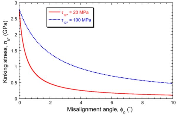
Figure 17: Predicted kinking stress as a function of misalignment angle, for epoxy-60wt% carbon composites, with two different interfacial shear strengths
In seasoned wood used for structural applications there is a cellular structure that has voids. The voids make it easier for the fibres to shear over in this way, so kink bands form more easily, and wood is particularly weak in compression.
Compressive failure when it occurs will be catastrophic in terms of the load-bearing capacity of the fibre-reinforced material, so that just as for ceramics, some material will be ejected from the failure site and the material will no longer be fit for purpose. Frustrated tennis players who smash their rackets against a hard surface and cause compressive failure of the fibre-reinforced composite tennis racket frame help to demonstrate this very point, as shown here.
Further reading
T.W. Clyne and J.E. Campbell, 2021, Testing of the plastic deformation of metals, Cambridge University Press.
M.F. Ashby and S.D. Hallam, 1986, The failure of brittle solids containing small cracks under compressive stress states, Acta Metallurgica 34, 497-510.
M.H. Jensen, 1999, Models of failure in compression of layered materials, Mechanics of Materials, 31, 553-564.
M. Knops, 2010, Analysis of failure in fiber polymer laminates: the theory of Alfred Puck, Springer-Verlag, Berlin.
M. Benamira, C. Hochard and A. Haiahem, 2011, Behaviour to failure of fibre mat reinforced composite under combined loading conditions, Composites: Part B, 42, 1412-1419.
Summary
- Toughness is the ability of a material to absorb energy from impact or applied stresses, and plastically deform without fracture.
- Failure occurs from flaws in the material which are impossible to avoid.
- Brittle fracture is hard to predict as it happens quickly. Ductile fracture is preferred, as it allows more time to replace a failing element without catastrophic failure occurring.
- The martensitic phase transformation can be exploited to toughen ceramics and metals.
- Crack deflection and fibre pull out toughen a material by increasing the surface area of a crack. This then requires more energy to be absorbed during propagation.
- Fibre-reinforced brittle materials have an increased Weibull modulus relative to their monolithic brittle matrices in the regime where they exhibit R-curve behaviour, making them more reliable to use than their monolithic matrix materials.
Questions
Quick questions
You should be able to answer these questions without too much difficulty after studying this TLP. If not, then you should go through it again!
-
Which is not a requirement when choosing the matrix of a zirconia toughened ceramic?
-
What is a condition for the tetragonal to monoclinic phase transformation if it is used to toughen a material?
-
Toughening is limited by the strength of the fibres in a short fibre composite.
Deeper questions
The following questions require some thought and reaching the answer may require you to think beyond the contents of this TLP.
-
When making extended grains in ceramics such as Si3N4, why is it important to cool the ceramic reasonably quickly after consolidation at high temperature?
-
Why do we toughen materials?
Going further
Books
T.W. Clyne and D. Hull, An introduction to Composite Materials, Cambridge University Press, 3rd edition, 2019
B.R. Lawn, Fracture of Brittle Solids, Cambridge University Press, 2nd edition, 1993
J.F. Knott and P.A. Withey, Fracture Mechanics: Worked Examples, CRC Press, 2nd edition, 2019
Q.-H. Qin and J.-Q. Ye (eds), Toughening Mechanisms in Composite Materials, Woodhead Publishing, 2015
C.B. Carter and M.G. Norton, Ceramic Materials: Science and engineering, Springer, 2nd edition, 2013
Crack deflection criterion derivation
The interface has fracture resistance, \( \Gamma_\text{i} \), whereas the bulk has a fracture resistance of \( \Gamma_\text{bulk} \).
For simplicity, we will assume the stiffness of the two layers is the same and consider the changing surface energies and strain energies to determine whether the crack deflects along the interface or propagates through the bulk.
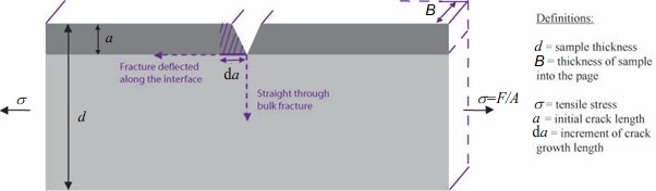
Consider the increment of crack growth of length \( {\rm{d}}a \) along the interface. This results in two energy changes: the interface is broken to form two surfaces, increasing the surface energy which opposes crack growth, together with a relaxation of the thin layer of material which favours crack growth.
The increment of surface energy is given by:
\[ {\rm{d}}{U_S} = {{\rm{\Gamma }}_\text{i}}B{\rm{d}}a \]
This assumes that the surface energy is the main contribution to the fracture resistance.
If we assume that the thin layer was constrained to have the same strain as the thick layer when it was bonded the release in stain energy will be:
\[ {\rm{d}}{U_E} = \; - \frac{1}{2}E{\varepsilon ^2}Ba{\rm{d}}a \]
where \( E \) is the common Young's modulus of each layer and \( \varepsilon \) is the strain to which the system is being subjected. Before the crack deflects, the main strain in the block, \( \varepsilon \), is:
\[ \varepsilon = \frac{\sigma }{E} = \frac{F}{{BdE}} \]
so that
\[ {\rm{d}}{U_E} = \; - \frac{1}{2}E{\left( {\frac{F}{{BdE}}} \right)^2}Ba{\rm{d}}a = \; - \frac{{{F^2}a}}{{2EB{d^2}}}{\rm{d}}a \]
The rate of change of the total energy, \( U \), with crack length increment, \( {\rm{d}}a \), is given by the equation
\[ \frac{{{\rm{d}}U}}{{{\rm{d}}a}} = \;\frac{{{\rm{d}}{U_S}}}{{{\rm{d}}a}} + \frac{{{\rm{d}}{U_E}}}{{{\rm{d}}a}} \]
By substitution
\[ \frac{{{\rm{d}}U}}{{{\rm{d}}a}} = {{\rm{\Gamma }}_\text{i}}B - \frac{{{F^2}a}}{{2EB{d^2}}} \]
The condition for interfacial cracking to begin is then
\[ \frac{{{\rm{d}}U}}{{{\rm{d}}a}} = 0 \]
Hence the applied force \( F \) at which this occurs is given by the expression
\[ F = Bd\sqrt {\frac{{2E{{\rm{\Gamma }}_\text{i}}}}{a}} \]
By comparison, the Griffith criterion for crack growth through the bulk can be given as:
\[ {F_{bulk}} = Bd\sqrt {\frac{{E{{\rm{\Gamma }}_\text{bulk}}}}{{\pi a}}} \]
For crack deflection, we clearly want \( F < F_\text{bulk} \). Therefore, the criterion for crack deflection can be given as:
\[ \frac{{{{\rm{\Gamma }}_\text{i}}}}{{{{\rm{\Gamma }}_\text{bulk}}}} < \frac{1}{{2\pi }} \]
Composite materials with suitably low values of interfacial fracture resistance will therefore be able to use crack deflection as their main toughening mechanism to increase the total path length, and therefore increase the work of fracture.
Fibres
Fibre choice is important when it comes to toughening a material. Fibres that are strong, will bond sufficiently well to the matrix and have the appropriate dimensions are required. In addition, the cost of processing the fibres needs to be taken into account: if the fibres are too expensive, they will not be practical for widespread use.
Examples of fibres used as reinforcing materials are polyacrylonitrile (PAN), carbon fibres, glass fibres and silicon carbide fibres.
Polyacrylonitrile (PAN) fibres
PAN is similar to polyethylene, but in every other CH2 group, one of the two hydrogen on the backbone is replaced with a nitrile group, -C≡N. Therefore, PAN is represented by the chemical formula (CH2CHCN)n, or, more succinctly, (C3H3N)n. PAN fibres are used in textiles where they are known as acrylic fibres. They are also used as precursor fibres to carbon fibres.
Carbon fibres
Carbon fibres are most often produced from PAN precursors, These precursors are stretched and pyrolyzed, i.e., heated in the absence of oxygen to decompose the fibres into carbon-rich residues – carbon fibres. In these fibres, graphitic planes are preferentially aligned parallel to the fibre axis., This gives the fibres very high stiffness along the fibre axis, but a low transverse stiffness. Depending on the production method, carbon fibres are referred to as either high modulus (HM) or high strength (HS) fibres. Typical fibre diameters are 5 μm.
Glass fibres
These are fibres made of a silica base with oxide additions. They are amorphous. The addition of oxides lowers the glass transition temperature of the silica by disrupting the rigid tetrahedral structure of silica that would otherwise form. This lower glass transition temperature makes the material easier to draw, but it reduces the maximum use temperature of the fibres relative to that of pure silica.
The fibres are made by melting the raw materials together and then pouring the viscous liquid through holes so that the fibres are formed under gravity. These fibres are easily susceptible to surface damage which would reduce their strength because this surface damage introduces surface flaws. To help prevent such surface damage, the fibres are often coated with an emulsifying polymer. This polymer protects the surface of the glass, and also acts as a coupling agent to help bond the fibre with the matrix by providing strong chemical bonds across the fibre-matrix interfaces.
Silicon Carbide
Silicon carbide in its crystalline form has strong sp3 bonding like diamond. Silicon carbide fibres have the desirable features of low density and high stiffness, together with good thermal conductivity. However, because of the way in which silicon carbide fibres are produced from organic precursors for reinforcement of ceramic composites, such fibres are more accurately described as Si-C-O fibres as they contain significant quantities of SiO2 and C. These Si-C-O fibres are microcrystalline / nanocrystalline materials.
Typically, silicon carbide fibres are 5 μm in diameter when used as reinforcements in ceramic composites and 100-150 μm in diameter, and higher purity, when used as reinforcements in metal matrix composites. The higher diameter fibres have a carbon or tungsten core around which the silicon carbide is deposited by chemical vapour deposition, and are purer than the finer Si-C-O fibres.
Carbon Nanotubes
Carbon nanotubes are very thin rolled up sheets of graphene which have very high tensile strengths because of their lack of grain boundaries and lack of large flaws − they cannot have large flaws because their diameter is too small for large flaws to exist. However, they are expensive to produce, and they are not suitable for toughening matrices. Therefore, despite their seemingly attractive mechanical properties, they are not seen in everyday use in composite materials designed for high toughness.
Toughness
The main way in which fibres toughen a material is by fibre pull out, rather than by exploiting the strength of the fibre itself. This means that larger diameter fibres, such as those used to toughen metal matrices, are more suitable than short fine fibres, such as carbon nanotubes, which are not suitable. A simple way of appreciating this is to recognise that larger diameter fibres each have a larger possible process zone volume either side of any propagating transverse crack to help absorb the energy of crack propagation, thereby helping to increase the toughness of the composite material.
Toughness of chocolate food products
As the experiments shown in the video on the testing of chocolate food products in https://dev.doitpoms.ac.uk/tlplib/toughen/intro.php demonstrate, the toughness of these products depends on their structure and composition, and the temperature at which the toughness is measured.
Chocolate is a material which is itself formed from a number of starting materials such as cocoa solids, cocoa butter, sugar and milk. Cocoa solids and cocoa butter are both derived from cocoa beans. Sugar and milk are optional additions to these two essential ingredients which enable chocolate to exhibit a wide range of sweetness, texture and taste for consumers.
Dark chocolate marketed as 90% or more cocoa can be regarded to a very good approximation as a homogeneous single material at length scales of 1 mm and above.
At refrigerator or freezer temperatures, e.g., 6 °C or less, a bar of dark chocolate behaves as a prototype brittle material. It will fail in bend testing in the elastic regime by fast fracture with what chocolate producers describe as a ‘firm snap’. The force required to fracture a bar will be relatively high, but not so high that an average adult will find it difficult to apply this force.
By contrast, a bar of dark chocolate equilibrated at a temperature of 37 °C (the average body temperature) will begin to deform plastically almost immediately when bend tested because there is little elastic deformation. Eventually, with a moderate force applied, it will break in a tearing manner, indicative of ductile fracture.
Therefore, between 6 °C and 37 °C, it is evident that dark chocolate undergoes a brittle → ductile transition. In this regard, dark chocolate behaves like b.c.c. metals such as ferrite and chromium, and viscoelastic materials such as elastomers. The strain rate is relevant in determining the precise brittle → ductile transition temperature. Just as for metals and viscoelastic materials like silly putty, the higher the strain rate at a given temperature within the brittle → ductile transition regime, the more likely the chocolate is to deform in a brittle manner.
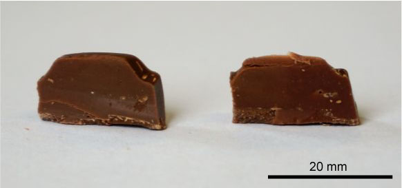
Photograph of a dairy milk bar in cross-section
The data for different types of chocolate products in https://dev.doitpoms.ac.uk/tlplib/toughen/intro.php demonstrate that, at room temperature, the chocolate with the highest cocoa content absorbs the least amount of energy in an impact test, i.e., it is the least tough. Adding milk to the product to make dairy milk chocolate is seen to increase its toughness relative to dark chocolate, both at room temperature and liquid nitrogen temperature.
A further increase at room temperature in the toughness is found when hard particles (nuts) and soft viscoelastic particles (raisins) are added to dairy milk chocolate to produce dairy milk fruit and nut bars.
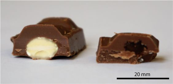
Photograph of a dairy milk fruit and nut bar in cross-section
However, at liquid nitrogen temperature, the advantage in toughness that dairy milk fruit and nut bars have over dairy milk chocolate is lost because the fruit component is brittle, and the dairy milk chocolate matrix is more stiff than at room temperature. Consequently, the hard particles of nut do not help to increase the surface area of cracks propagating in the chocolate matrix at liquid nitrogen temperature as efficiently as they do at room temperature. Therefore, within experimental error, dairy milk chocolate bars and dairy milk fruit and nut bars at liquid nitrogen temperature are equally tough.
Snickers is a chocolate bar in which a layer of nougat, and a layer of both caramel and peanuts are all encased in a thick surface coating of milk chocolate.
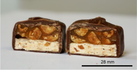
Photograph of a Snickers bar in cross-section
The combined viscoelastic and adhesive behaviour of both the nougat and the caramel enables the Snickers bar to be very tough at room temperature, as determined by the impact test demonstration in https://dev.doitpoms.ac.uk/tlplib/toughen/intro.php where the impact is side on to the Snickers bar.
Interestingly, Snickers is also seen to be reasonably tough at liquid nitrogen temperature in this experiment because of the way in which the complex microstructure of the Snickers bar helps to absorb the impact of the pendulum. An experiment undertaken at much higher rates of strain than attainable with this pendulum experiment would be necessary to have Snickers bars show brittle behaviour at liquid nitrogen temperature, similar to that shown by the dark chocolate in the pendulum experiments.
The principles established from the impact test demonstrations in https://dev.doitpoms.ac.uk/tlplib/toughen/intro.php can be used to study other chocolate food confectionery. Some open-source references to such studies are:
D. Schab, L. Tiedemann, H. Rohm and S. Zahn, Application of a tensile test method to identify the ductile-brittle transition of caramel, 2022, Foods, 11, art. 3218, see the pdf from https://doi.org/10.3390/foods11203218
Y.-Y. Chen, X.-Y. Zhou, S.-H. Qian and J.-H. Yu, Effect of sugar and milk powder addition on the mechanical properties and texture of chocolate, 2022, Journal of Oleo Science, 71,1577-1589, see the pdf from https://doi.org/10.5650/jos.ess22148
S.M.I. Birch, J. Bates, M. Bell, K.A. Christofidou, C.L. Corkhill, V. Hearnden, E.A. Lopez, L.C. Mason, A. Southworth and J.S. Dean, Bending bad—testing caramel wafer bars (#TestATunnocks), 2021, Physics Education, 56, art. 055002, see the pdf from https://doi.org/10.1088/1361-6552/abfece
D. Bikos, G. Samaras, P. Cann, M. Masen, Y. Hardalupas, C. Hartmann, J. Vieira and M.N. Charalambides, Effect of micro-aeration on the mechanical behaviour of chocolates and implications for oral processing, 2021, Food and Function, 12, 4864-4886, see the pdf from https://doi.org/10.1039/d1fo00045d
Academic consultants: Rob Thompson and Kevin Knowles (University of Cambridge)
Content development: Julianna Nowaczek and Beth Peers
Photography and video: Julianna Nowaczek and Beth Peers
Web development: Lianne Sallows and David Brook
DoITPoMS is funded by the UK Centre for Materials Education.
Additional support for the development of this TLP came from the Worshipful Company of Armourers and Brasiers