Uses of ternary alloys
There are many industrially important ternary alloys. The ability to have more than two components in an alloy opens up possibilities to improve mechanical properties beyond the limits of binary alloys: reduced melting points for solder, maximising solid solution strengthening without changing phase, extending the temperature range of desirable phases. This section provides a few examples of useful or interesting ternary systems.
Ti–Al–V
Titanium exists in a hcp structure (\( \rm{\alpha} \)) at high temperatures (above 882°C) and a body centred cubic structure (\(\rm{ \beta} \)) at low temperature (below 882°C).
Alloying additions will often act to stabilise one of these fields – extending its stable temperature range (e.g., \( \rm{\alpha} \) being stable to lower temperatures). Additions can sometimes act to form a eutectoid too.
One of the most important titanium alloys is 6 wt.% Al 4 wt.% V and balance Ti. Aluminium is an \( \rm{\alpha} \) stabiliser and vanadium is a \( \rm{\beta} \) stabiliser. This alloy lies in the \(\rm{ \alpha + \beta} \) two phase field at room temperature.
The exact microstructure will depend on the extent of hot working and heat treatments but slow cooled Ti–6Al–4V will crystallise as \( \rm{\beta} \) initially and then on further cooling \( \rm{\alpha} \) will nucleate and grow to give a Widmanstätten microstructure (laths of \( \rm{\alpha} \) in a \( \rm{\beta} \) matrix).
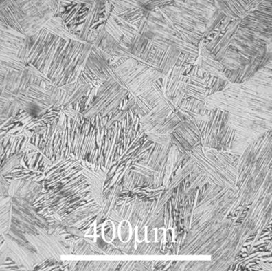
Figure 41: Reflected light micrograph of a Ti-6Al-4V alloy showing both \( \rm{\alpha} \) and \( \rm{\beta} \) phases. Image from DoITPoMS micrograph library 54, a mixed α+β Ti alloy with a Widmanstätten microstructure
This microstructure has good strength, toughness and fatigue resistance. This alloy is light weight and biocompatible, and has been used in applications such as prosthetics, in the aerospace industry and for hydraulics systems.
Ti–Ni–Nb
Near equimolar binary alloys of Ti and Ni (also known as Nitinol) show exceptional shape memory behaviour (see Superelasticity and Shape Memory Alloys TLP). It can be deformed at low temperature and when it is heated it can recover the deformation and take on its original shape again. This property is possible because of an austenite/martensite like transition that occurs in this alloy.
The phase change is associated with a change in shape but not a change in volume. The dimension of a sample will show a hysteresis loop upon heating and cooling.
Nitinol and related alloys have had significant use in the medical field (notably as stents as they can be fitted in a less invasive procedure than traditional stainless-steel stents). They’ve also been used in electrical switches, aircrafts and as vibration dampeners.
Adding a third element to NiTi alloys can alter the mechanical properties of the alloy but they can also alter the temperature at which the phase transformation (which mediates the shape memory behaviour) occurs.
The addition of Nb reduces the temperature at which the austenite phase begins to convert to the martensitic phase. This increases the width of the hysteresis loop and allows medical devices made from these allows to be stored over a wider range of temperatures.
The addition of Nb pushes the martensite start temperature and the austenite start temperature apart. This increases the width of the hysteresis loop and allows these alloys to be stored over a wider range of temperatures.
A micrograph of an alloy with compositions 47 at. % Ni 44 at. % Ti 9 at. % Nb is shown below in its as-cast state. This alloy is commonly used in pipe coupling. This image was taken using an SEM in backscattered mode so the elements with the highest atomic numbers (Nb: 41, Ni: 28, Ti: 22) will appear brightest.
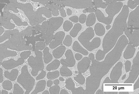
Figure 42: Backscatter SEM image of a 47 at. % Ni 44 at. % Ti 9 at. % Nb alloy showing primary dendrites and interdendritic eutectic. Image by Oliver Reed
This composition lies in the two-phase TiNi + (Ti, Nb) field. Nb and Ti show complete solid solubility when Ti is in the \( \rm{\beta} \) phase. (Ti, Nb) refers to this phase which spans the Nb-Ti side of the ternary.
The microstructure is dominated by the eutectic reaction involving these two phases. Prior to the reaction there is extensive growth of TiNi dendrites as the primary solid. The interdendritic space is then filled by eutectic intergrowth of TiNi and (Ti, Nb) showing typical lamellar eutectic microstructure.
Au–Pb–Sn
While there has been a move away from lead-based solders now, there was a period where Pb-Sn solders were the gold standard for soldering in electronic devices.
One problem encountered was the diffusion of gold from plating diffusing into the solder. The addition of gold to these alloys could cause embrittlement, reducing the efficacy of the join.
The Au–Pb–Sn system was studied to learn more about the impact of gold on solder.
It is quite an interesting ternary system as it contains a pseudobinary. The intermediate phase AuSn melts congruently. A vertical section drawn from the Pb corner to the AuSn composition is a true binary (all the tie lines for alloys along the section lie in the plane of the section).
The pseudo-binary is a thermal divide. Alloys that lie on one side of the thermal divide cannot evolve to produce melts or solids that lie on the other side of the thermal divide. This allows each side of the diagram to be considered in isolation.
The gold-poor half of the diagram is more commonly studied as it is rare for the concentration of gold in solder joints to exceed 50 wt.%.
The gold-poor half of the diagram is relatively simple, with two class II (ubergang, U) reactions and a terminal class I (eutectic, E) reaction.
The diagram below shows the liquidus projection of the gold-poor side of the ternary phase diagram.
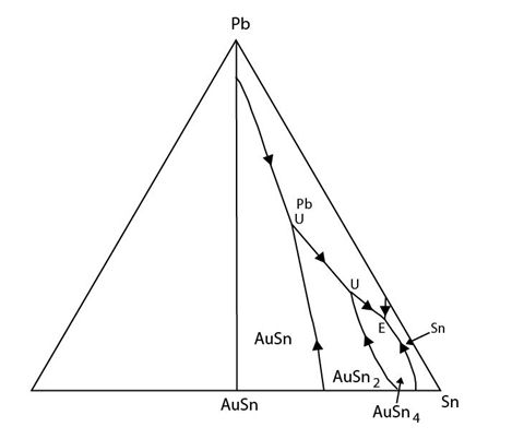
Figure 43: Au-poor side of the Au-Pb-Sn ternary system – separated from the rest of the system by a thermal divide. This partial ternary system shows three invariant reactions. Adapted from https://matdata.asminternational.org/apd/viewPicture.aspx?dbKey=grantami_apd&id=10759796&revision=422525
A micrograph with composition 5.2 wt.% Au 10 wt.% Pb balance Sn in its as cast state is shown below. This composition is just off the composition of the terminal eutectic.
The phases involved in the terminal eutectic reaction are Sn, AuSn4 and Pb.
The composition of this sample lies in the Sn + L field so the primary solid is dendritic Sn. This is followed by co-crystallisation of Sn and AuSn4 as the composition of the remaining liquid reaches the eutectic valley. The composition of the liquid moves down temperature to the eutectic point where the liquid is exhausted in the ternary eutectic reaction:
\[ \rm{ L \rightleftharpoons Sn + Pb + AuSn_4} \]
The system is fully solid. The Sn dendrites, secondary AuSn4 and ternary eutectic intergrowth can all be seen in the micrograph.
AuSn4 is an intermetallic phase which forms needle-like crystals rather than dendrites or spherical precipitates as would be expected for a metallic phase.
Cu–Ni–Sn
Alloys from the Cu–Ni–Sn system have become increasingly important in the aerospace and electronics industries. They have excellent thermal and electrical conductivity, high strength and good wear resistance. They are ideal alternatives to Cu–Be alloys, whose production creates toxic dust.
This system has a lot of potential applications as a bearing material.
A micrograph of an alloy with composition 12 at.% Ni 3 at.% Sn balance Cu is shown below. This image was taken using an SEM in backscattered mode. The elements with the highest atomic numbers (Sn: 50, Cu: 29, Ni: 28) appear brightest.
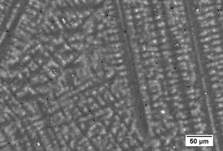
Figure 44: Backscatter SEM image of an alloy of composition 12 at. % Ni 3 at. % Sn balance Cu. Image by James Hogg
The Cu-rich corner of the ternary phase diagram features a class II (ubergang) reaction. The alloy lies in the (Cu, Ni) phase field so an fcc solid with Cu and Ni forms first. The composition of the liquid moves away from the bulk composition towards the (Cu, Ni) + Cu0.85Sn0.15 eutectic valley. Once the liquid reaches the eutectic valley (Cu, Ni) and Cu0.85Sn0.15 solidify.
The composition of the liquid moves down temperature towards the invariant class II point. When it reaches the point the quasi-peritectic reaction occurs:
\[ \rm{L + Cu, Ni \rightleftharpoons (Cu, Ni)_3Sn + Cu_{0.85}Sn_{0.15}} \]
The (Cu, Ni) dendritic phase reacts with the liquid to produce the two more tin-rich phases. There is an intergrowth of the two tin bearing phases in the interdendritic region.
Duplex stainless steels
Stainless steels are a family of steel alloys that are based on the Fe – Ni – Cr ternary system, although they will often contain other elements (such as Mo and N). Cr stabilises the (\( \rm{\alpha} \)) ferrite phase while Ni stabilises the (\( \rm{\gamma} \)) austenite phase. There are four main types of stainless steels: ferritic, austenitic, martensitic (like ferritic but with higher carbon content) and duplex (contains ferrite and austenite).
These alloys are useful because of their good mechanical properties, cleanability (ability to remove contaminants from the surface and corrosion resistance.
Their corrosion resistance comes from the chromium present in alloy, which forms a coherent, chromium oxide layer on the surface of the alloy, which protects it from further oxidation.
Duplex stainless steels are stronger than fully ferritic stainless steels (though at the expense of some ductility).
These alloys solidify as fully ferritic. Nucleation and growth of the austenite phase occurs during subsequent heat treatments.
Below is an optical micrograph of a relatively fine-grained sample of duplex stainless steel.
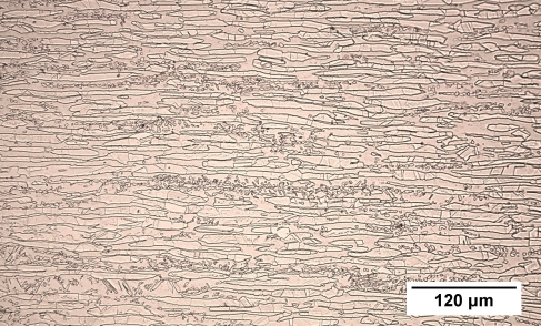
Figure 45: Reflected light micrograph of a coarse-grained duplex stainless steel
It is clear from the micrograph that there are two phases present as there are grains of two distinct colours. The phases cannot be differentiated from optical microscopy alone. The application of ferrofluid (FeO) which clusters on the magnetic ferrite grains would allow the two phases to be distinguished.
Olivine–clinopyroxene-plagioclase
Ternary phase diagrams can also be used in the study of ceramic systems.
The olivine–clinopyroxene–plagioclase system is of vital importance to the study of Earth sciences as it describes the melting, evolution and solidification of the Earth’s mantle.
Each endmember in this system is not a single element as they have been in previously discussed systems. Each corner represents the composition of a specific mineral. Typically, these are forsterite (the magnesium-rich endmember of olivine, Mg2SiO4), diopside (a magnesium and calcium bearing clinopyroxene, CaMgSi2O6) and anorthite (calcium endmember of the plagioclase feldspars, CaAl2Si2O8).
Another vital difference between this ternary system and the metallic ternary systems discussed above is that this system is incredibly simplified.
The number of components in natural systems such as the mantle is much greater than three. For example, 11 major oxides are required to describe a mudstone. This classification of major oxides does not account for minor contributions from a vast array of elements which can have huge effects on the kinetics of the system (and consequently the phases that have time to form).
The effective number of components in these complex systems must be reduced for them to be analysed with ternary phase diagrams. This can be done by assuming that a component is in excess. Once this assumption is made, that component can be projected away from (consider a tetrahedron projected from one corner becoming a triangle) reducing the number of components in the system. The number of components can also be reduced by combining components. Both approaches, while simplifying, come with a loss of information.
The olivine – clinopyroxene – plagioclase ternary system is only a section of the basalt tetrahedron. It is simplified by projecting from the mineral quartz.
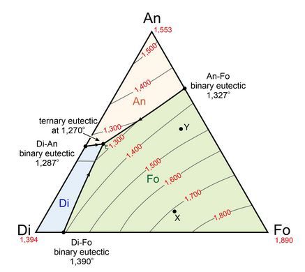
Figure 46: Liquidus projection of the Anorthite (An)– Diopside (Di) – Forsterite (Fo) ternary system. Image source: figure 8.55 from https://opengeology.org/petrology/8-igneous-phase-diagrams-and-phase-equilibria/?print=print
Below is a micrograph of a thin section of a peridotite from the Island of Rum. It is a 30 μm section of the rock (most minerals become translucent at this thickness) viewed in plan polarised light in a transmission optical microscope.
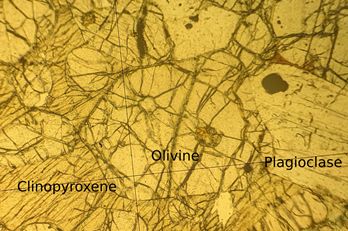
Figure 47: A transmission microscopy image in plane polarised light of a thin section from a peridotite on Rum. The sample is from the Igneous Petrology reference series, Department of Earth Sciences, University of Cambridge
The same thin section is viewed between crossed polars as the interaction of polarised light with minerals is useful in identifying them. The width of the field of view is 1mm.
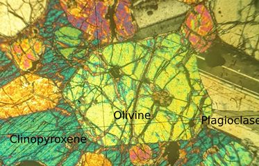
Figure 48: A transmission microscopy image of the sample between crossed polars. the sample is from the Igneous Petrology reference series, Department of Earth Sciences, University of Cambridge
These micrographs show grains with very different morphologies to those seen in metallic micrographs. This is due to the minerals present having strongly preferred growth directions and non-cubic crystal systems.
Melts from the mantle nearly always lie in the olivine + liquid phase field. Olivine is crystallised first; this is often followed by olivine + plagioclase crystallisation then by the olivine + clinopyroxene + plagioclase eutectic reaction.
This reaction is not an invariant reaction but a univariant reaction, even though it includes four phases (liquid, olivine, clinopyroxene and plagioclase). This is because the system considered here is quaternary (four components) and according to the Gibbs phase rule, there is an additional degree of freedom relative to true ternary systems.
There is evidence for this solidification history in the micrograph. The most prominent crystal (labelled ‘olivine’) is likely a primary olivine while the smaller, equally brightly coloured crystals are secondary olivine crystals. There are plagioclase crystals into the largest olivine and between smaller olivine crystals. This implies that the olivine came before the plagioclase. The clinopyroxene is the last phase to appear in the solidification history. It fills whatever space is left by the olivine and plagioclase crystals. Many of the olivine crystals in the left of the micrograph are enveloped in a single clinopyroxene grain (appears blue in crossed polars). These olivine crystals must predate the clinopyroxene growing around them.